Author: Hayden
MPO patch cables are the foundation of modern high-speed data center cabling. From 400G SR8 to 800G DR8 deployments, selecting the correct MPO patch cable ensures low insertion loss, accurate lane mapping, and stable AI workload performance.
This complete guide explains fiber types (OM4, OM5, OS2), MPO-12 vs MPO-16 connectors, polarity types (A/B/C), breakout configurations (1:1, 1:2, 1:4), and deployment best practices for 400G and 800G networks.
What Is an MPO Patch Cable?

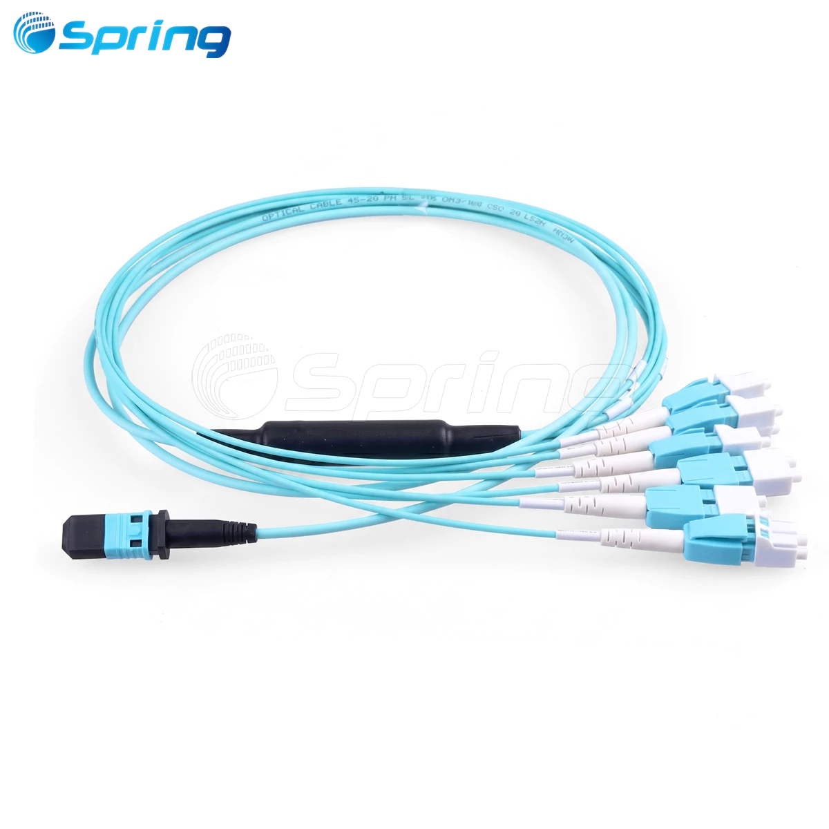
An MPO (Multi-Fiber Push-On) patch cable is a high-density fiber optic cable designed for parallel optical transmission. It integrates multiple fibers-commonly 8, 12, or 16 fibers-into a single connector.
MPO patch cables are widely used for:
·400G and 800G transceiver interconnects
·AI data center clusters
·High-density rack environments
·Spine-leaf architectures
Using the correct MPO patch cable minimizes return loss, reduces signal degradation, and ensures reliable high-speed transmission.
MPO Patch Cable Types: OM4, OM5, OS2


Choosing the correct fiber type is critical for 400G and 800G deployments.
| Module Type | Recommended Fiber | Typical Distance |
|---|---|---|
| 400G SR8 / SR4 | OM4 or OM5 | 50–100 m |
| 800G SR8 | OM5 MPO patch cable | Short-reach, SWDM support |
| 400G DR4 / DR8 | OS2 | Up to 500 m |
| 800G DR4 / DR8 | OS2 | Up to 500 m |
OM5 MPO patch cable is ideal for 800G SR modules because it supports shortwave WDM (SWDM) and improves scalability.
OS2 single-mode MPO patch cable is required for DR modules to maintain low attenuation over medium distances.
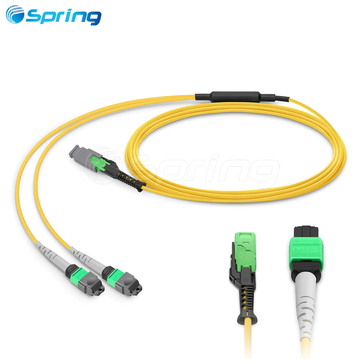
MPO Fiber Count: MPO-12 vs MPO-16
Fiber count must match the transceiver interface.
| Module | Fiber Requirement | Connector Type |
|---|---|---|
| 400G SR8 / DR8 | 16 fibers | MPO-16 |
| 400G SR4 / DR4 | 8 fibers | MPO-12 |
| 800G SR8 / DR8 | 16 fibers | MPO-16 or 2×MPO-12 |
| 800G SR4 / DR4 | 8 fibers | MPO-12 |
Using mismatched fiber counts can cause link failure or unused channels.
MPO-16 connectors are increasingly common in 800G AI network deployments due to lane density requirements.
MPO Polarity Guide (Type A, B, C)


Polarity ensures correct Tx/Rx alignment between modules.
| Polarity | Description | Typical Use |
|---|---|---|
| Type-A | Straight-through | Legacy systems |
| Type-B | Fiber reversed | Direct 400G/800G module links |
| Type-C | Pairwise flipped | Structured backbone |
For direct 400G and 800G connections, Type-B polarity is generally recommended.
Incorrect polarity leads to lane mismatch and link initialization failure.
Determine Breakout Configuration (1:1, 1:2, 1:4)
Modern AI data center networks frequently use breakout architectures to maximize port utilization.
Breakout configuration defines how a high-speed port (such as 800G) splits into multiple lower-speed links.
Example Scenario

An 800G switch port connects to two 400G server NICs.
If the 800G module uses:
One MPO-16 port
→ Use 1 × MPO-16 to 2 × MPO-12 breakout cable
This splits 16 fibers into two 8-fiber 400G links.
Two MPO-12 ports
→ Use 2 × MPO-12 patch cords
Each MPO-12 port connects independently.
Common Breakout Types
| Breakout Type | Use Case |
|---|---|
| 1:1 | 400G to 400G |
| 1:2 | 800G to 2×400G |
| 1:4 | 400G to 4×100G or 800G to 4×200G |
Breakout Configuration Must Match
Before deployment, confirm:
Module interface type (MPO-16 or dual MPO-12)
Network topology (leaf-spine, TOR, AI fabric)
Port speed configuration (native or split mode)
Incorrect breakout design may cause:
Lane mapping errors
Link failure
Packet loss
Downtime in AI clusters
Selecting MPO Patch Cables for 400G and 800G
When choosing an MPO patch cable, verify:
·Fiber type (OM4 / OM5 / OS2)
·Fiber count (MPO-12 / MPO-16)
·Polarity (Type-B recommended)
·Breakout structure (1:1 / 1:2 / 1:4)
·Connector gender (module male → cable female)
·Endface type (APC for 400G/800G, UPC for 40G/100G)
·Cable length (distance + 10–20% slack)
Correct selection ensures network stability and long-term scalability.
MPO Patch Cable Quick Selection Checklist
| Parameter | Selection Basis | Options |
|---|---|---|
| Fiber Type | Based on module | OS2 / OM4 / OM5 |
| Fiber Count | Based on interface | MPO-12 / MPO-16 |
| Polarity | Architecture | Type-A / B / C |
| Breakout | Port configuration | 1:1 / 1:2 / 1:4 |
| Length | Physical distance | ____ meters |
| Connector Gender | Module requirement | Male / Female |
| Endface | Module spec | UPC / APC |
FAQs About MPO Patch Cables
Q1: Can OM4 MPO patch cables support 800G SR8?
OM4 may work for very short distances, but OM5 is recommended for SWDM support.
Q2: Which polarity is required for 400G SR8?
Type-B polarity is typically used for direct connections.
Q3: Why do some 800G modules use dual MPO-12?
To improve thermal and mechanical balance while supporting 16 lanes.
Q4: Can APC and UPC MPO cables be connected?
No. Mixing endfaces causes high return loss.
Q5: What breakout cable is needed for 800G to 2×400G?
An MPO-16 to 2×MPO-12 breakout cable.
Q6: What is the difference between MPO-12 and MPO-16?
MPO-16 supports full 16-lane 400G/800G SR8 or DR8 modules.
link this article internally to:
MTP vs MPO Connectors: Procurement Guide for High-Density Data Centers
MPO Connector: High-Density Fiber Connectivity Explained
MPO patch cable selection directly impacts 400G and 800G network reliability.
The right combination of:
OM5 MPO patch cable
MPO-16 connector
Type-B polarity
Correct breakout configuration
ensures stable AI data center performance and future-proof scalability.
Use this guide as your technical reference when planning modern high-density fiber networks.