Author: Alisa alisa@springoptic.com
As the effort to efficiently deploy higher-density fiber networks in data centers and high-speed networks grows, the need for higher-density fiber cables is increasing rapidly. The MPO (Multi-fiber Push-On) connector is the key technology developed to meet these demands. In this article, we will look at the structure, types, uses, and differences between MPO and MTP connectors to give a clear understanding of this high-density fiber solution.


What is an MPO Connector?
The MPO (Multi-fiber Push-On) connector is a multi-fiber push-fiber style connector that feeds multiple fibers into a linear array in a single ferrule. This enables efficient termination of multi-fiber ribbon cables in high-density indoor applications.
The MPO connector has established itself as the standard connector interface for high-density trunk cables and is widely used in patch panels, servers, switches, and other equipment. A single MPO connector can replace many SC or LC connectors and carries fiber densities as much as 12 times greater in the same area. This saves a great deal of space as well as simplifying the installation process.
MPO connectors have been standardized by international standards such as IEC-61754-7 and the US standard TIA 604-5 to ensure interoperability and reliability.

Structure and Types of MPO Connectors
The structure of the MPO connector consists of a molded rectangular plastic housing incorporating a "keying" mechanical system for alignment and fiber position orientation. When the keying is "up", fiber 1 will be found to the left side of the connector. The connector has a push-pull locking system that produces a "click" to assure a rapid and reliable mating connection.
MPO connectors are available in the following fiber densities:
8 fiber, 12 fiber, 24 fiber, 32 fiber, 48 fiber, and special high-density 60 fiber and 72 fiber configurations.
The connectors that are most generally used are the 12-fiber and 24-fiber connectors:
MPO-12: The first connector widely used in data centers.
MPO-24: The perfect solution for 40G (with 8 fibers) and 100G (with 24 fibers).
Note that the 12-fiber and 24-fiber MPO connectors come in the same shell size, but the 24-fiber connector incorporates a second row of 12 fibers. Likewise, the MPO 48 fiber and 72 fiber connectors have 4 and 6 rows of fibers, respectively.
MPO male connector: One of the more basic ideas behind MPO design. Male connectors are supplied with stainless steel alignment pins, while female connectors are pinless. All MPO device ports are males; therefore, the MPO patch cables are female. This design provides good alignment and helps to prevent fiber damage.
Deep Comparison: MPO vs MTP Connectors
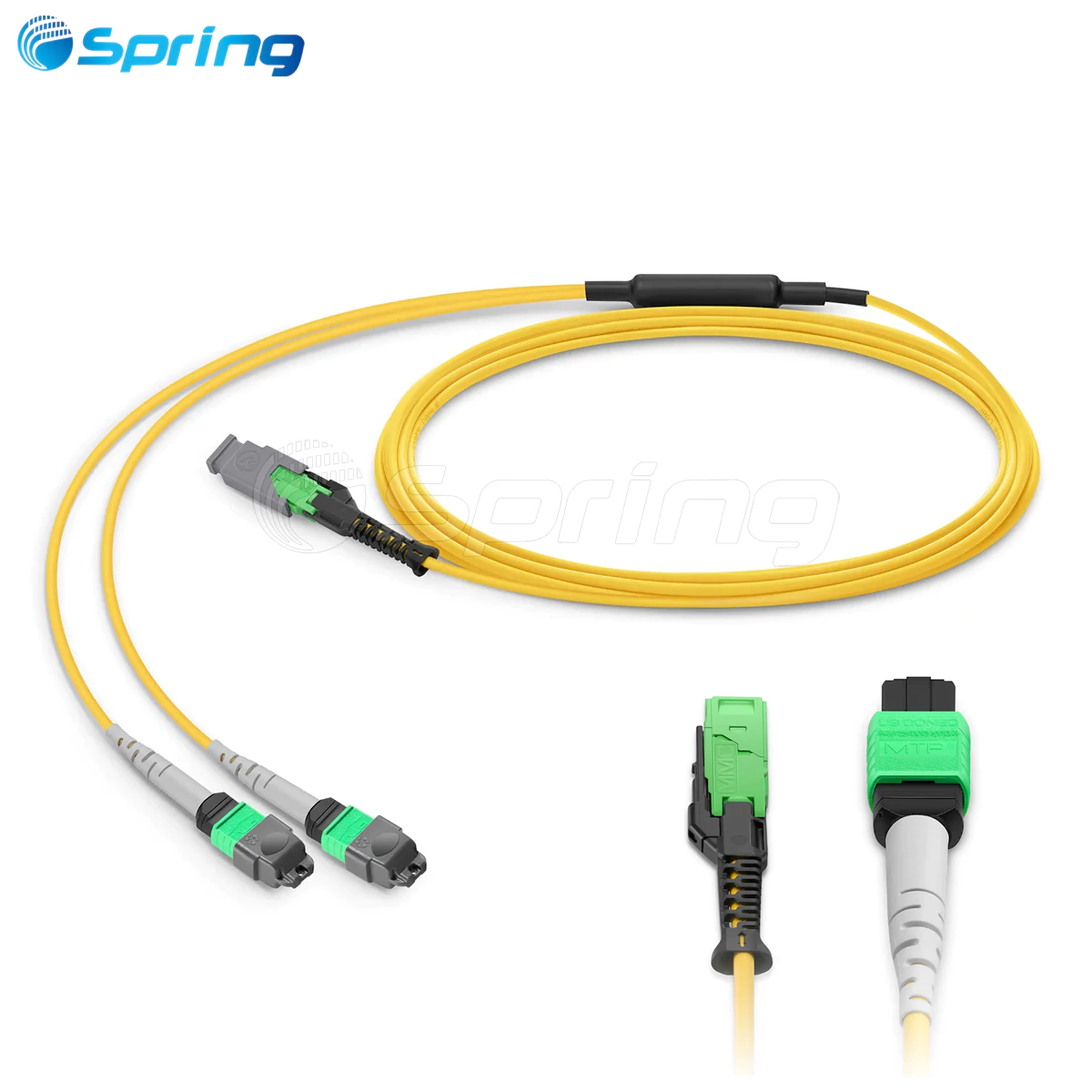
While the term "MPO" is often used interchangeably with the term "MTP," it is essential to know the differences in meaning. The term MTP is a trade name of US Conec, and is the abbreviation for "Multi-fiber Termination Push On" connectors. MTP connectors have several design advantages which are proprietary:
·Floating ferrule insures better alignment and performance under load.
·Oval guide pins help to align and ensure durability.
·Removable housing insures easy field gender changes and ferrule polishing.
·Improved spring design facilitates management of fiber spacing.
·Metal pin clips and centering springs help to prevent loss of pins and fiber damage.
·All MTP connectors are conformant to MPO, however, not all MPO connectors can claim the high-end features of MTP.
MPO Polarity Management

In fiber optic systems, polarity ensures proper connections of the optical fibers between the transmitter and receiver. Because of the high density of MPO connectors, polarity management is made more difficult, employing mainly three different styles of polarity management:
·Type A (Straight-through): Fiber 1 at position 1 connects to fiber 1 at the connector adjacent to it. The direction of keying between the two connectors is different.
·Type B (Reversed): Fiber 1 at position 1 connects to fiber 12 at the connector adjacent to it (in MPO-12). The direction of keying between the two connectors is the same. Used principally in architectures requiring 40G/100G.
·Type C (Pairwise Reversed): Fiber 1 connects to position 2, fiber 2 connects to position 1. Each pair of fibers is independently reversed. Used principally in architectures requiring 1G/10G.
MPO Alignment Mechanism and Performance Considerations
MPO connectors maintain close tolerances through the use of two stainless steel alignment pins. This method, however, is deficient in performing the task of simultaneously aligning a plurality of fibers, since edge separation of fibers will increase offset in the lateral direction and risk combinatorial tolerance build-up.
Main factors which affect the performance of MPO connectors:
·The mismatch of fiber geometrical forms.
·Fresnel reflection due to air gaps or contamination.
·Misalignment due to manufacturing tolerances.
·In applications requiring great density, low-loss budget, and high-end performance, MPO specialized test equipment should be used to achieve maximum performance.
MPO Connector Certification Standards
MPO connector manufacturers must conform to strict protocols of interoperability:
IEC 61754-7 (International standard).
EIA/TIA-604-5 (FOCIS 5, U.S. standard).
These specifications outline the physical characteristics of the connector, including the pin and guide hole dimensions of the female and male interfaces. In addition, the MPO connectors must meet the parameters established in IEC PAS 61755-3-31 for the geometry of the end face of the fiber, including polishing angle, height of fiber projection, and maximum difference in height of the fibers.
Practical Applications of MPO Connectors
Data Center Backbone Applications
MPO Connectors, utilizing pre-terminated plug-and-play backbone cables, provide high-density connections between active equipment. As compared to duplex cables, MPO trunk cables occupy less space, simplifying cable management and expediting the deployment process.
Parallel Fibre Applications
MPO is the de facto standard interface for parallel fiber applications, which transmit and receive information across several fibers simultaneously:
·40Gbps and 100Gbps multimode fiber applications (40GBASE-SR4 and 100GBASE-SR4).
·200Gbps and 400Gbps applications utilizing 8-fiber MPO operating with 4 fibers transmitting and 4 receiving.
·800Gbps applications utilize 16-fiber MPO with 8 fibers transmitting and 8 receiving, achieving 100Gbps transmission rates.
·Future 1.6Tbps applications will employ advanced configurations of MPO.
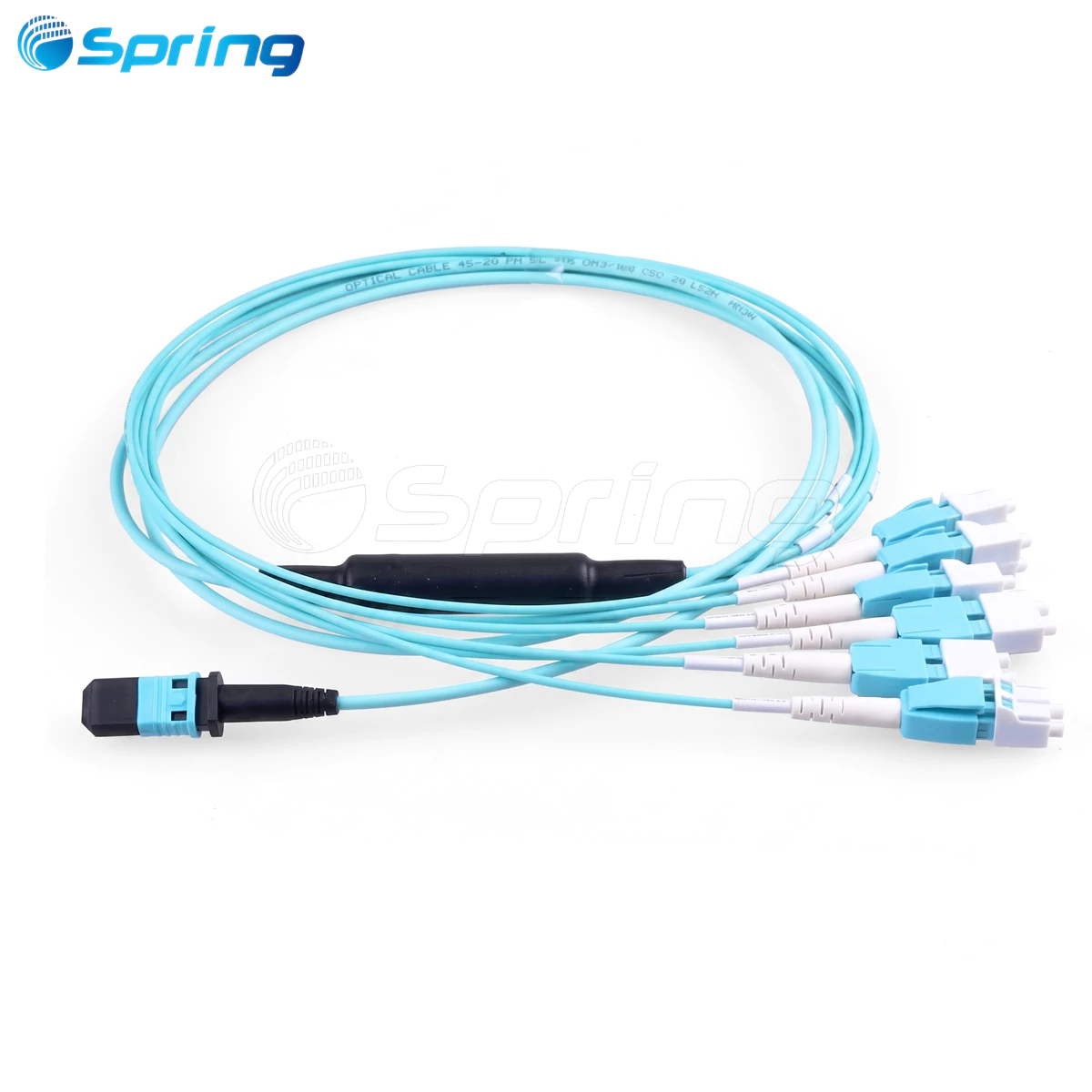
Branching Applications
Branch cables, terminated on one end with an MPO connector and the other with duplex connectors, enable high-speed switch ports to switch to several lower-speed switch or server ports. For instance, an 8-fiber MPO interface on a 100Gbps switch port can connect to four 25Gbps servers.
Conclusion
MPO connectors have become an indispensable component of high-density fiber networks. Their excellent space efficiency, flexible configuration options, and reliable performance make them crucial in multiple sectors, from data centers to high-speed computing environments. Understanding the types of MPO connectors, polarity management, and the distinctions between MPO and MTP connectors is essential for designing and deploying efficient fiber infrastructure.
As network speeds evolve toward 400G, 800G, and even higher rates, MPO technology will continue to evolve, providing a solid foundation for next-generation fiber networks. Selecting the appropriate MPO solution will help you optimize space utilization and total cost of ownership while maintaining high performance.