Hello, technical audience, network engineers, and O&M professionals! Welcome to the final installment of our technical deep dive into optical communication hardware.
We are wrapping up our hardware journey by discussing a topic that controls link stability but is often misunderstood on-site: Fiber End-Face Polish Types (PC, UPC, and APC).
Let's clear up one point immediately: "PC" on a fiber label does not mean computer. It indicates the physical geometric shape of the ceramic ferrule's tip.

Visual Identification Guide: Color and Shape
You can instantly identify these three distinct polish profiles on a patch panel using two simple visual indicators: color coding and tip shape.
End-Face Polishing Classification Table
| Polish Type | Connector Housing Color | Geometric Tip Profile | Standard Return Loss | Primary Use Case |
| PC (Physical Contact) | Blue | Slightly Spherical (Appears Flat) | ≥40dB | Legacy networks, low-speed links |
| UPC (Ultra Physical Contact) | White / Gray | Extended Convex Dome | ≥50dB | High-speed datacenters (10G–400G) |
| APC (Angled Physical Contact) | Green | 8° Angled Spherical Cut | ≥60dB | CATV, FTTx, Coherent Long-Haul |
The Visual Indicators
The Blue Connector (PC): Represents standard Physical Contact. The end-face is polished into a micro-spherical dome to minimize air gaps, but it looks flat to the eye.
The White Connector (UPC): Represents Ultra Physical Contact. It features an extended, highly precise convex dome polish that allows closer core-to-core contact than standard PC.
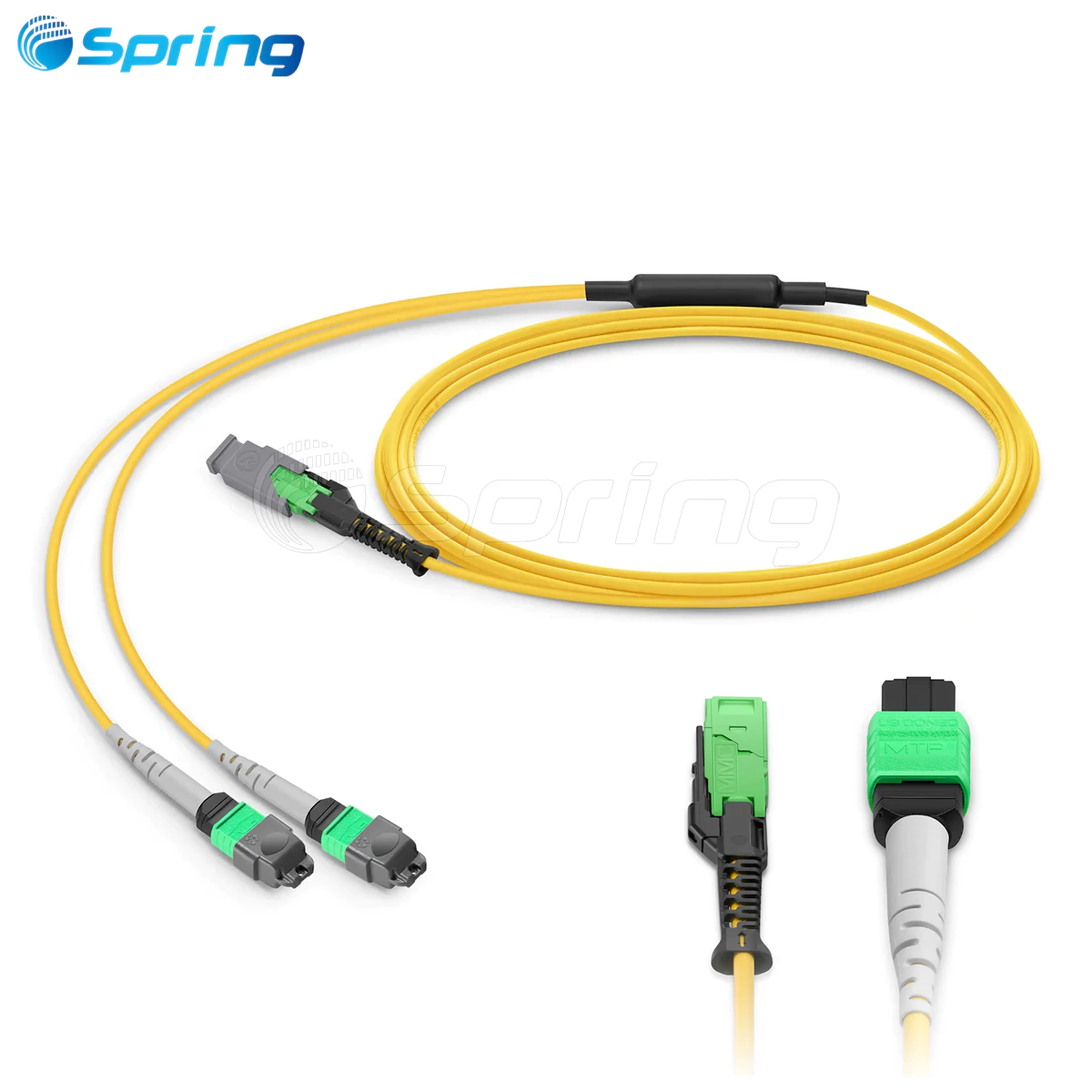
The Green Connector (APC): Represents Angled Physical Contact. The tip is cut and polished at a strict 8-degree angle. This slant is easily visible when inspected from the side.
Why the 8° Angle is Critical for Return Loss
To understand why these polishes exist, you must focus on Return Loss-the measurement of how much optical signal reflects back toward the transmitter. Reflected light creates optical noise, degrading high-speed laser performance.
Return Loss measures the ratio of reflected light to transmitted light, expressed in decibels (dB). A higher Return Loss value means a cleaner link with less back-reflection.
Standard PC and UPC polishes reflect light straight back down the core toward the laser source.
The APC connector's 8-degree angle completely changes this behavior. When light reflects off an APC end-face, the 8-degree angle forces the reflected rays to bounce out of the core and safely into the surrounding fiber cladding, where they are absorbed harmlessly.
Because of this angled design, companies like Spring Optical specify APC connectors for video networks, analog systems, and long-haul links where extreme signal purity is non-negotiable.
The Unbreakable Matching Rules

When patching lines, follow these two mandatory matching laws:
Interface Shape Consistency: An LC connector only goes into an LC port.
End-Face Polish Consistency: Blue stays with Blue (UPC/PC). Green stays with Green (APC).
Why You Must NEVER Mix APC and PC/UPC
If you plug a green APC connector into a blue UPC adapter port, you create an operational disaster. Because one tip is angled at 8 degrees and the other is flat, the physical fiber cores will not touch.
This creates a massive physical gap inside the adapter, causing insertion loss to skyrocket and return loss to plummet. The light signal will drop drastically, and the massive back-reflection can easily damage sensitive transceiver lasers.
Real-World Failure Case: The Mixed Panel Disaster
During a data center backbone upgrade to a 100Gbps network, an enterprise suffered severe packet loss, and several switch ports refused to come online.
The Troubleshooting Process:
We ran an Optical Time-Domain Reflectometer (OTDR) test on the failing segment. The trace showed a massive return loss drop down to 35dB-far below the standard 50dB network threshold.
We physically inspected the patch cabinets and discovered the root cause: a third-party installation crew had mistakenly plugged blue SC-PC patch cords directly into green SC-APC bulkheads inside the main distribution rack.
The mismatched angles prevented proper core contact, blocking the light path.
We pulled out the mismatched blue cords and replaced them with correct green SC-APC patch cords. Return loss immediately recovered to a clean 58dB, packet loss dropped to zero, and the 100G links stabilized instantly.
O&M Field Troubleshooting Matrix
If you experience high attenuation or link dropouts, use this quick guide to diagnose your polish issues:
Symptom: Intermittent Signals or High Bit Error Rates
Check: Look for mixed polish types across your jumpers. Ensure a technician didn't bridge a blue and green interface inside an enclosure.
Symptom: High Attenuation Immediately Following a Patch
Check: Inspect the APC connector seating. Angled connectors rely on a tiny structural alignment key on their shell. If that key isn't fully seated in the slot, the angles won't align, creating massive signal loss.
Symptom: Sudden Loss After Cleaning
Check: Ensure you didn't scrub an APC connector across a flat cleaning block. For APC strings, you must follow the 8-degree slant of the face to avoid flattening the precise factory polish.
FAQ
What are PC, UPC, and APC fiber connectors?
These acronyms represent the geometric physical shape of the ceramic ferrule's tip. They control the Return Loss (the amount of light reflected back to the source). PC is slightly spherical, UPC features an extended precision convex dome, and APC is cut and polished at a strict 8-degree angle.
How do I visually identify PC, UPC, and APC fiber connectors?
The fastest way is color coding. APC (Angled) connectors are always Green. PC (Standard) connectors are Blue, and UPC (Ultra) connectors are typically White or Gray. The APC angle is also visible side-on.
Why does the APC connector have the lowest return loss?
The APC connector has the lowest return loss (≥60dB) because its 8-degree angled end-face ensures that any light reflecting off the tip does not bounce back into the fiber core toward the laser. Instead, the angle forces reflected light into the surrounding fiber cladding, where it is harmlessly absorbed.
Can I plug an APC (Green) connector into a UPC (Blue) port?
No, you must never mix them. Plugging a green APC (angled) connector into a blue UPC (flat) port creates a massive physical gap inside the adapter because the geometry does not match. This creates skyrocketing insertion loss, plummeting return loss, and severe signal failure.
In what types of networks are APC connectors mandatory?
APC connectors are mandatory for analog systems, video transmission (CATV), passive optical networks (FTTx), coherent long-haul links, and fiber sensing systems that have an extremely low tolerance for signal back-reflection.
Final Summary
Choose your fiber end-face polish based on your application's tolerance for back-reflection: Use PC for basic low-speed networks, UPC for standard high-speed enterprise data centers, and APC for ultra-pure video, broadband, or telco trunks. Keep your colors matched, keep your ferrules clean, and your fiber links will run at peak performance.