

As FTTH (Fiber to the Home) rollout, 5G backhaul expansion, and smart city infrastructure projects continue to grow worldwide, fiber optic networks are becoming denser and more complex than ever before. Telecom operators are no longer deploying fiber only for residential broadband. Modern networks must also support surveillance systems, industrial communication, intelligent transportation, edge computing, and hyperscale data transmission.
To meet these high-capacity demands, many operators are shifting from traditional cable pulling methods to air blown fiber systems and fiber microduct systems. These solutions allow faster deployment, easier upgrades, and significantly better utilization of crowded underground duct space.
However, the success of a blown fiber installation depends on more than just the fiber cable itself. One of the most overlooked but critical components in the entire system is the microduct connector (also known as a microduct coupler).
A microduct connector is a sealed, high-performance fitting used to join microducts in air blown fiber systems. Its primary job is to maintain pressure integrity, precise duct alignment, and environmental protection. Poor connector performance can lead to air leakage, drastically reduced fiber blowing distance, water ingress, connector separation, and costly installation failures in the field.
This comprehensive guide explains:
What a microduct connector is and how it works
Different connector types (Straight, Reducer, Gas Block) and their specific applications
Critical requirements for direct buried (DB) connectors
Step-by-step installation best practices
Common troubleshooting issues and solutions
How to choose the right connector for FTTH and blown fiber networks
What Is a Microduct Connector?
A microduct connector is a specialized mechanical coupling device designed to join two sections of microduct within a fiber optic duct network. Unlike standard electrical conduit fittings, these connectors are specifically engineered for high-pressure telecom environments that require absolute airtight sealing and stable airflow continuity.
In modern fiber infrastructure, high-quality microduct connectors are essential to maintain:
Pressure Integrity: Withstanding up to 15-16 bar of pressure during the blowing process.
Mechanical Retention: Gripping the duct tightly to prevent separation under tension or pressure.
Waterproof/Environmental Protection: Preventing ingress of water, mud, and contaminants.
Internal Alignment: Ensuring a smooth, step-free transition between ducts to prevent fiber snagging.
They are widely deployed in FTTH access networks, 5G backhaul, smart city initiatives, data center campus networks, and industrial communication systems.
How Microduct Connectors Work: The Mechanics of Sealing
Microduct connectors create a robust, sealed mechanical connection between two duct sections, usually employing a push-fit mechanism for speed and efficiency.
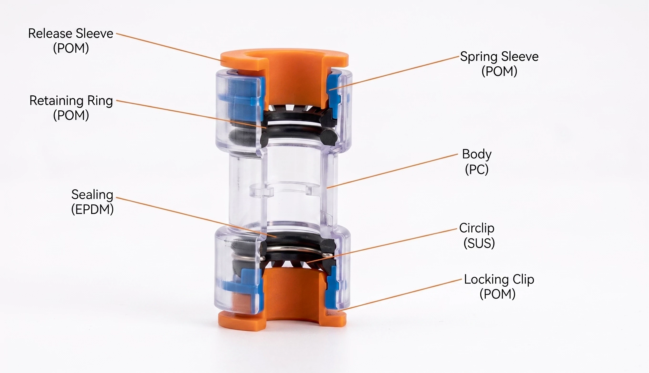
The Internal Structure
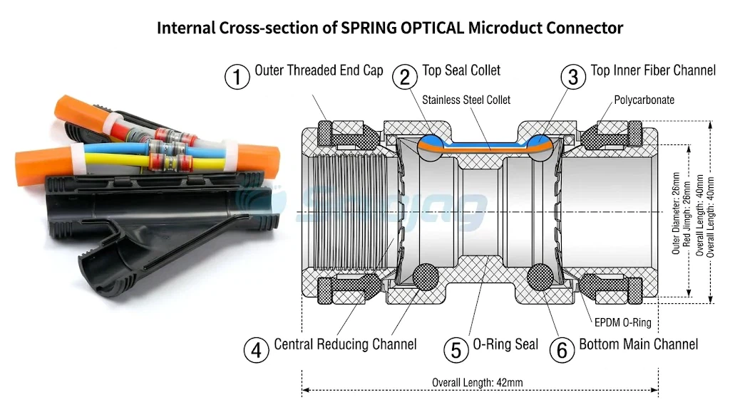
Internal Locking Teeth (Collet): Usually made of stainless steel or high-strength engineering plastic, these teeth grip the outer surface of the microduct securely once inserted.
Sealing Rings (O-Rings): Typically made of NBR or EPDM rubber, these provide the airtight seal around the duct.
Transparent Connector Body: Allows installers to visually verify that the microduct is fully and correctly inserted past the sealing rings.
Safety Locking Clips: Red or blue clips that are inserted under the collet cover to prevent accidental release of the duct due to vibration or pulling.
During installation, compressed air generates the force required to propel fiber units through the network. Even a minute leakage point at a connector can disrupt the laminar airflow, reducing efficiency and preventing the cable from reaching its intended destination.
Pro Tip: In long-distance FTTH backbone projects, field technicians often discover that poor connector sealing is the primary reason for reduced blowing performance and incomplete cable installation.
Types of Microduct Connectors
Different telecom environments require specific connector configurations to maintain airflow continuity and long-term network reliability.
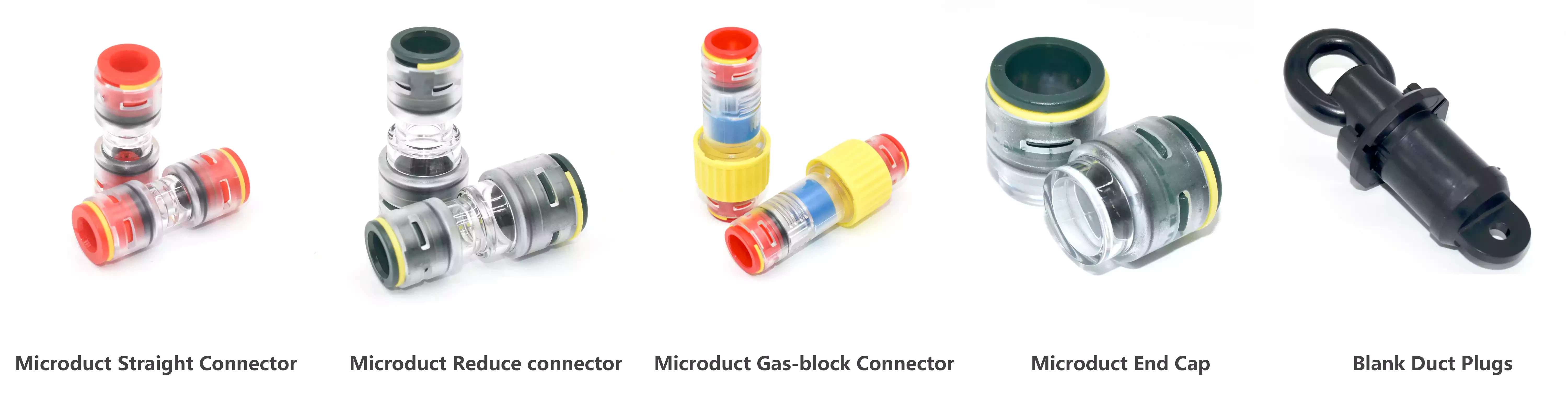
1. Microduct Straight Connector
Used to connect two microducts of the same outer diameter (OD). These are the workhorses of residential FTTH rollout, creating continuous pathways from the central office to distribution points.
Common Sizes: 7/5.5mm, 10/8mm, 12/10mm, 14/12mm, 16/13mm.
2. Microduct Reduce Connector
Designed to seamlessly connect microducts of different diameters. They are critical when transitioning from larger backbone ducts to smaller branch ducts leading to individual customer premises.
Example: Transitioning from a 14/10 mm distribution duct to a 10/8 mm drop duct.
Technical Importance: High-quality reducers are engineered with smooth internal tapers to minimize airflow turbulence and prevent the fiber from hitting a "step" during blowing.
3. Microduct Gas Block Connector (Water Block)
Specialized sealing connectors designed to prevent the migration of gases or water inside the duct system between different environments.
Applications: Metro tunnel infrastructure, transitioning from outdoor underground chambers to indoor premises, or utility networks prone to hazardous gas accumulation.
Function: They feature an internal sealing mechanism that can be tightened around the fiber after it has been blown through, isolating the duct sections.
4. Microduct End Cap
Used to temporarily or permanently seal unused microduct ends.
Importance: Crucial during phased FTTH rollouts to preserve unused pathways, keeping them clean, dry, and ready for future fiber deployment without needing to re-clean the duct.
Key Features of High-Quality Microduct Connectors
In demanding underground fiber networks, connector quality directly affects installation efficiency and long-term maintenance costs. Look for these essential features:
IP68 Waterproof Protection
For underground and outdoor infrastructure, IP68 rating is non-negotiable. Buried systems are constantly exposed to groundwater, flooded trenches, and soil moisture. Standard indoor connectors will fail in these conditions, leading to duct contamination that makes future blowing impossible without expensive excavation.
High Pressure Resistance
Air blown fiber systems typically operate between 10–15 bar (145–217 PSI). Poor-quality connectors may deform, crack, or leak under this intense pressure, causing the installation to fail midway.
Transparent Body Design
This is a critical field installation advantage. It allows technicians to visually verify full duct insertion past both O-rings and ensure internal cleanliness. This simple feature significantly reduces installation errors and accelerates field inspection.
Locking Clip Safety Mechanism
Locking clips provide vital mechanical security post-insertion, preventing connector separation caused by ground vibration (near roads), backfilling forces, or accidental pulling during other maintenance activities.
UV and Corrosion Resistance
Outdoor, above-ground connectors must be made of UV-stabilized materials to prevent brittleness over time. All internal metal components (like locking teeth) should be corrosion-resistant (e.g., stainless steel) to handle humid underground environments.
Direct Buried (DB) Microduct Connectors Explained
Direct buried microduct connectors are specifically engineered for underground installation without the need for additional protective enclosures (like manholes or handholes).
Compared to standard fittings, DB connectors must withstand harsh environmental stress over a 20–25 year service life.
| Feature | Standard Connector | Direct Buried (DB) Connector |
|---|---|---|
| Waterproof Capability | Basic Moisture Resistance | True IP68 (Submersible) |
| Mechanical Strength | Limited | Reinforced to withstand soil loading & compaction |
| Underground Suitability | Indoors or inside closures only | Suitable for direct burial in trench |
| Impact Resistance | Moderate | High (withstands backfilling) |
Soil Pressure and Moisture Protection
Underground ducts face continuous stress from wet soil, frozen ground expansion, and traffic vibration. High-quality DB connectors maintain perfect duct alignment and sealing stability under these crushing forces. Reliable moisture protection is paramount; if water enters and freezes, or if mud dries inside the duct, future fiber deployment becomes impossible.
Key Applications Across Fiber Infrastructure
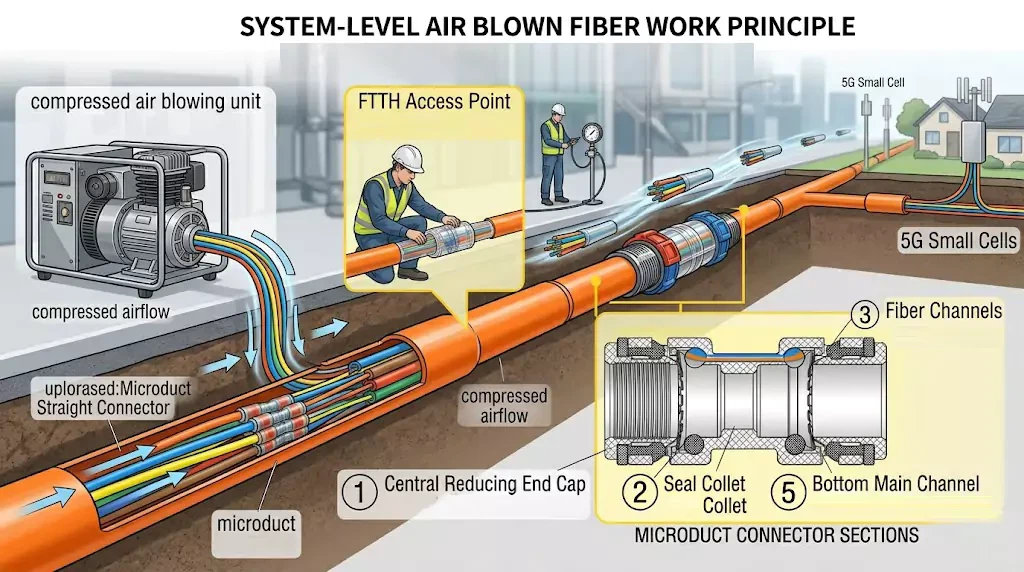
FTTH/FTTP Networks
Reliable connectors allow operators to scale duct infrastructure quickly. In residential neighborhoods, connector reliability directly affects deployment speed, branch installation simplicity, and future scalability without reopening trenches.
5G Backhaul & Small Cells
5G requires high-density fiber in congested urban environments. Microduct systems maximize limited underground space, and reliable, high-pressure connectors are essential to ensure efficient installation across complex urban pathways.
Smart City & IoT Infrastructure
Supporting traffic monitoring, surveillance, and public Wi-Fi, microduct connector systems allow for flexible network expansion as smart city needs evolve over decades.
Data Center Campus & Industrial Networks
Simplifies future upgrades between buildings without major civil works. In industrial settings, durable connectors handle vibration, chemical exposure, and extreme temperature variations.
How to Install a Microduct Connector: 4 Steps to Success
Proper installation is critical for maintaining sealing performance.
Step 1 - Preparing the Microduct
Inspect the duct carefully for cracks, oval deformation, or scoring. Verify the outer diameter (OD) and inner diameter (ID) match the connector specs. Clean the first few inches of the duct surface to remove dirt or grease.
Step 2 - Correct Cutting (Crucial!)
Microduct ends must be cut perfectly square (90 degrees) and clean using a professional, sharp microduct cutter.
| Cutting Mistake | Result on Installation |
|---|---|
| Angled cut | Incomplete insertion, seal damage, gap causing turbulence |
| Rough/Burred edge | O-ring damage during insertion, causing leaks |
| Oval deformation | Will not pass through O-rings, forcing insertion damages connector |
Step 3 - Connector Insertion
Push the microduct firmly into the connector. You will feel an initial resistance as it passes the first O-ring, and then a second definitive click as it bottoms out against the internal stop, having passed the second O-ring. Visually verify through the transparent body that the duct is fully inserted.
Step 4 - Locking Clip Installation
Immediately install the safety locking clips (red or blue) under the collets at both ends. This secures the connection against vibration and accidental release. Give the duct a gentle tug to confirm retention.
Common Problems and Troubleshooting
| Problem | Potential Causes | Recommended Solutions |
|---|---|---|
| Air Leakage during blowing | 1. Incomplete insertion. 2. Damaged O-ring due to bad cut. 3. Incorrect connector size. | 1. Push duct fully past internal stop. 2. Recut duct squarely and replace connector. 3. Verify OD/ID matching. |
| Poor Blowing Distance | 1. Air pressure loss at connectors. 2. Internal step causing fiber snag. 3. Duct contamination. | 1. Pressure test connectors. 2. Ensure square cuts; use high-quality reducers. 3. Sponge clean duct before blowing. |
| Connector Separation | 1. Missing locking clips. 2. Excessive tension or ground movement. | 1. Always install locking clips. 2. Ensure proper sand bedding in trench to absorb movement. |
| Water Ingress discovered later | 1. Using non-IP68 connectors outdoors. 2. Improper installation. | 1. Only use Direct Buried rated connectors underground. 2. Follow installation best practices meticulously. |
Industry Standards and Testing for Reliability
Ensure your chosen connectors comply with recognized international standards:
EN 50411-2-8: The key European standard for microduct connectors regarding functional performance and environmental reliability within fiber management systems.
IP68 Rating: Verifies waterproof sealing performance under submerged conditions (e.g., 1.5m depth for 30 minutes), essential for Direct Burial.
Pressure & Temperature Testing: High-quality connectors are tested to withstand 15–16 bar pressure and temperature cycling (e.g., -40°C to +65°C) without losing sealing integrity.
Frequently Asked Questions (FAQ)
What is the difference between a microduct coupler and a connector?
In the telecom industry, these terms are often used interchangeably. Both refer to the mechanical fittings used to join microduct sections while maintaining pressure and alignment.
Can standard microduct connectors be directly buried?
Generally, no. You must specify Direct Buried (DB) connectors for underground installation without an enclosure. They are specifically reinforced to handle soil pressure, compaction, and constant moisture ingress (IP68).
How do you prevent air leakage in microduct systems?
The four golden rules are: Use a square-cut duct, clean the duct surface, ensure full insertion past the O-rings (visually verify), and install safety locking clips.
Can microduct connectors be reused?
While some designs allow for disconnection and reuse, most telecom operators recommend replacing a connector once it has been removed from a buried installation to guarantee absolute sealing reliability for the next blowing operation.
Why Quality Microduct Connectors Matter
While microduct connectors are relatively small components in the overall budget of an FTTH or 5G rollout, they play a disproportionately massive role in the network's build quality and long-term viability.
Selecting the right, high-quality, IP68-rated, and transparent microduct connector:
Ensures efficient fiber blowing to maximum distances.
Protects the underground infrastructure from water and mud ingress for decades.
Reduces costly field failures and excavation rework during network activation.
Whether you are a telecom operator, an EPC contractor, or an FTTH deployment company, investing in reliable connector solutions is essential for building durable, scalable, and future-ready fiber networks.
Need Expert Help Selecting the Right Connectors?
Don't let a small component jeopardize a major fiber project. Our engineering team provides:
Technical support for complex network designs
OEM customization for specific duct dimensions
IP68-tested and EN 50411-2-8 compliant connector solutions
[Contact Our Fiber Infrastructure Specialists Today] to request samples or a quotation for your next deployment.