

Introduction
In every FTTH, FTTx, and structured cabling network, the quality of fiber termination has a direct impact on long-term network reliability. Even when premium optical cables and high-performance equipment are used, poor fiber splicing or improper fiber management inside a fiber optic terminal box can lead to increased insertion loss, signal attenuation, and costly maintenance.
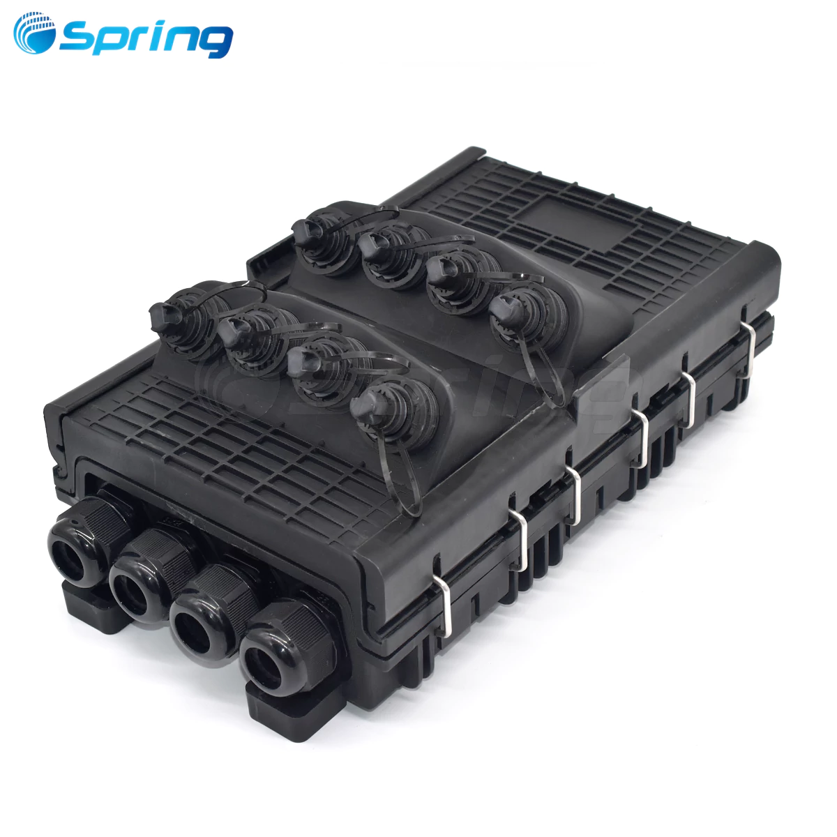
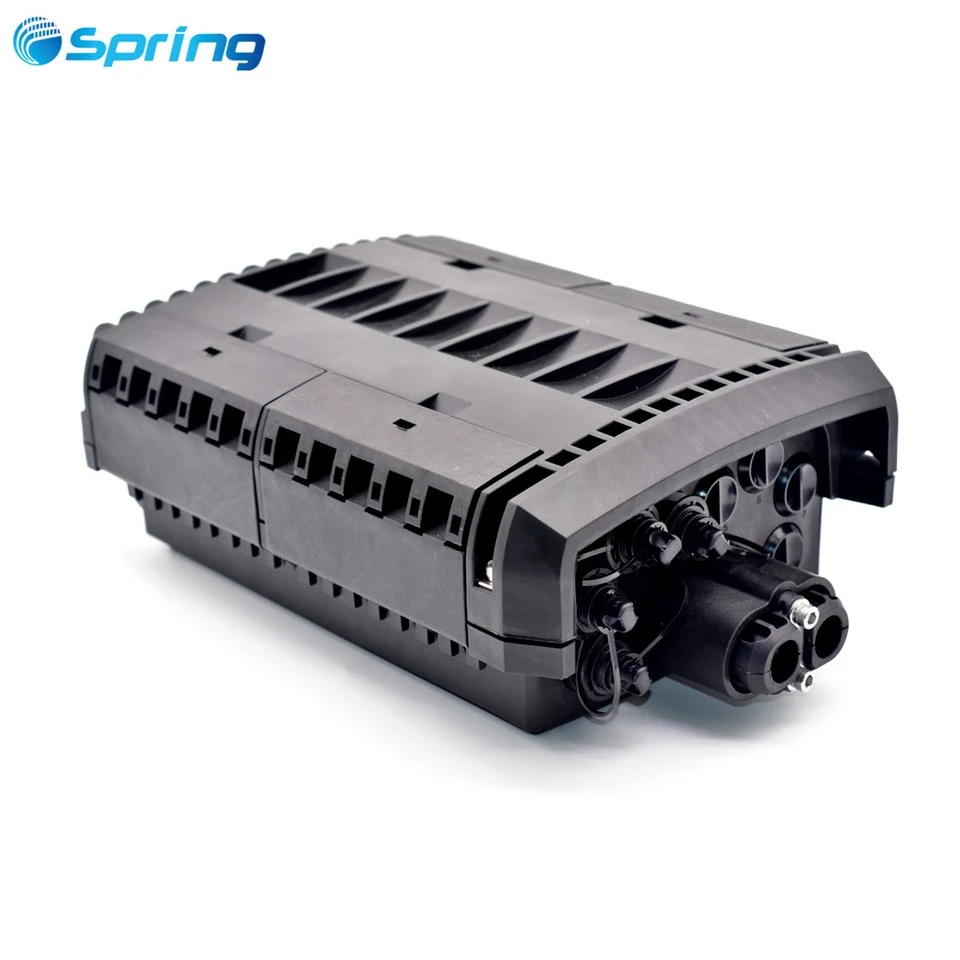
A fiber optic terminal box is typically installed at the endpoint of a horizontal fiber cable, serving as the final connection point before optical equipment or subscriber access. It protects fiber splices, organizes pigtails, and provides a secure interface through optical adapters.
Professional installation is more than simply completing a fusion splice. Proper cable preparation, accurate cleaving, low-loss splicing, organized fiber routing, and final OTDR verification all contribute to building a reliable optical network.
In this guide, we'll walk through the complete installation process-from tool preparation and fiber end-face preparation to fusion splicing, fiber routing, and final inspection-following industry best practices used by professional fiber installers.
Why Proper Fiber Splicing Matters
Every fusion splice introduces a certain amount of optical loss. Although today's fusion splicers can achieve splice losses below 0.03 dB, poor workmanship can significantly increase attenuation and degrade overall network performance.
Proper installation provides several important benefits:
- Lower insertion loss
- Reduced return loss
- Improved long-term network stability
- Better mechanical protection for fiber splices
- Easier maintenance and future upgrades
- Longer service life of the fiber infrastructure
For FTTH deployments, enterprise LANs, data centers, and backbone networks, standardized splicing procedures are essential for maintaining consistent optical performance.
Tools and Materials Required
Before beginning installation, prepare all necessary tools and materials.

Essential Tools
Fiber fusion splicer
Precision fiber optic cleaver
Fiber stripper
Cable stripping pliers
Needle-nose pliers
Lint-free wipes
99% Isopropyl alcohol (IPA)
Heat-shrink splice protection sleeves
Cable ties
Masking tape
Optical Time Domain Reflectometer (OTDR)
Keeping all tools clean and properly calibrated is equally important. Contaminated V-grooves, worn electrodes, or a damaged cleaver blade can all negatively affect splice quality.
Installation Demonstration

For this demonstration, we use:
- 8-port Fiber Optic Terminal Box
- SC Fiber Optic Adapters
- Single-mode SC Pigtails
- 8-core Outdoor Single-Mode Central Loose Tube Fiber Optic Cable
This configuration represents a common deployment in FTTH access networks and building distribution systems.
Step 1: Prepare the Fiber End Faces
Preparing high-quality fiber end faces is the foundation of successful fusion splicing.
The preparation process consists of three stages:
- Stripping
- Cleaning
- Cleaving
Each stage directly affects splice quality.
Install the Terminal Box Components

Begin by securely installing all eight SC adapters into the terminal box.
Feed the outdoor optical cable into the enclosure, leaving approximately 15–20 cm (6–8 inches) of cable reserved inside the box for termination.
Secure the cable firmly before removing the outer jacket and exposing the strength members according to the cable design.
Prepare the Pigtails

Insert each SC pigtail connector into the rear of the corresponding adapter.
Since all pigtails typically use white buffer coatings, identify each one by numbering them from 1 through 8.
These numbers will later correspond to the feeder cable fibers following the standard TIA/EIA 598 fiber color code:
Blue/Orange/Green/Brown/Slate/White/Red/Black/Yellow/Violet/Rose/Aqua
Proper identification prevents wiring errors during installation.
Perform Pre-Fiber Routing

One commonly overlooked technique is pre-routing the fibers before fusion splicing.
Because terminal boxes have limited internal space, routing both the feeder fibers and pigtails into the splice tray before splicing allows you to determine the correct fiber lengths.
Position the future splice protector location and trim both fibers accordingly.
After splicing, the fibers will naturally fit into the tray without unnecessary bending or excess slack, making cable management significantly easier.
Strip and Clean the Fiber

Before stripping, slide a heat-shrink splice protection sleeve onto the pigtail.
Never forget this step, as the sleeve cannot be installed after the splice is completed.
Using a precision fiber stripper, remove approximately 2–3 cm of coating from each fiber.
Hold the stripper perpendicular to the fiber with a slight inward angle, then strip smoothly along the fiber axis.
Inspect the bare fiber carefully.
If any coating residue remains, clean the fiber thoroughly using a lint-free wipe moistened with isopropyl alcohol.
The fiber should appear completely clean before cleaving.
Cleave the Fiber

Fiber cleaving is arguably the most important part of end-face preparation.
A high-quality cleave produces a perfectly flat fiber end, allowing the fusion splicer to align both fibers accurately.
Operate the cleaver using smooth, controlled movements.
Avoid excessive force, which may cause:
- Angled cleaves
- Broken fibers
- Surface cracks
- Burrs
- End-face defects
For this example, Fiber No. 1 is matched with the blue feeder fiber.
Once both fibers have been properly stripped, cleaned, and cleaved, they are ready for fusion splicing.
Step 2: Perform Fiber Fusion Splicing
Fusion splicing forms the permanent optical connection between the feeder cable and the pigtail.
Before beginning, configure the fusion splicer according to the fiber type being used.
Typical parameters include:
- Pre-fusion arc current
- Main fusion current
- Arc duration
- Fiber feed distance
Different fiber types may require different parameter settings.
Maintain a Clean Fusion Splicer

During installation, regularly clean:
- V-grooves
- Electrodes
- Objective lenses
- Fiber clamps
- Splicing chamber
Even microscopic dust particles can increase splice loss.
Monitor Splice Quality

Observe each splice carefully.
Common defects include:
- Air bubbles
- Thick splice joints
- Thin splice joints
- Fiber separation
- Incomplete fusion
If any abnormal condition is detected, re-cleave both fibers and perform the splice again.
After completion, verify the estimated splice loss displayed by the fusion splicer.
As a general guideline, splice losses below 0.03 dB indicate excellent splice quality.
Repeat the same procedure for all remaining fibers according to the standard color sequence.
Once every fiber has been successfully spliced, the termination process moves to fiber management.
Step 3: Organize the Fibers Inside the Splice Tray


Fiber routing is often underestimated, yet it plays a major role in long-term reliability.
Proper fiber management protects the splices while making future maintenance much easier.
Install each splice protector into the designated holder according to the standard color sequence.
Since the fibers were pre-routed earlier, simply follow the same routing path.
Begin by organizing the pigtails neatly around the splice tray.
Then arrange the feeder fibers.
Maintain smooth curves throughout the routing process.
Avoid:
- Sharp bends
- Twisted fibers
- Crossed fibers
- Excessive tension
Maintain the minimum recommended bend radius specified by the cable manufacturer.
Finally, secure the pigtails using masking tape or cable ties where appropriate to prevent movement caused by vibration or accidental impact.
A clean, organized splice tray is not only aesthetically pleasing-it also improves long-term network reliability and simplifies future servicing.
Step 4: Perform Final Inspection and Testing
Installation should never be considered complete until all quality inspections have been performed.
Visual Inspection

Check that:
- No fibers are pinched
- No fibers exceed the minimum bend radius
- Fibers are neatly organized
- Splice protectors are fully seated
- No fibers overlap excessively inside the tray
OTDR Testing

Use an Optical Time Domain Reflectometer (OTDR) to verify optical performance.
The OTDR should confirm:
- Normal splice attenuation
- No abnormal reflection
- No excessive insertion loss
- No hidden faults along the link
Testing verifies that the installation meets network performance requirements before deployment.
Seal the Terminal Box

After testing is complete, close the terminal box cover.
Tighten all screws evenly to ensure proper sealing.
A correctly sealed enclosure protects the internal fiber splices from dust, moisture, and environmental contamination.
Common Installation Mistakes to Avoid
Even experienced technicians occasionally encounter avoidable issues.
Some of the most common mistakes include:
- Forgetting to install the heat-shrink sleeve before splicing
- Inadequately cleaned fiber end faces
- Poor cleave quality
- Incorrect fiber identification
- Excessively tight fiber bends
- Overlapping fibers inside the splice tray
- Dirty fusion splicer electrodes or V-grooves
- Skipping OTDR verification after installation
Avoiding these mistakes greatly improves installation quality and long-term network reliability.
Best Practices for Professional Fiber Termination
To achieve consistent, low-loss fiber installations, follow these best practices:
- Always use calibrated tools.
- Keep all fiber end faces perfectly clean.
- Replace worn cleaver blades when necessary.
- Clean the fusion splicer regularly.
- Follow the standard fiber color sequence.
- Leave sufficient slack for future maintenance.
- Maintain the recommended fiber bend radius.
- Test every completed link using an OTDR.
Professional installers understand that careful preparation and attention to detail often save hours of troubleshooting later.
Conclusion
Proper fiber termination involves much more than simply completing a fusion splice.
Every stage-from cable preparation and fiber end-face preparation to fusion splicing, fiber routing, and OTDR testing-contributes to the overall performance and reliability of the optical network.
By following standardized installation procedures and industry best practices, installers can consistently achieve low splice loss, organized fiber management, simplified maintenance, and long-term network stability.
Whether you are deploying FTTH access networks, enterprise fiber infrastructure, data centers, or campus networks, mastering these fiber splicing techniques is essential for building a high-quality fiber optic system that will continue to perform reliably for years to come.
Frequently Asked Questions
What is a fiber optic terminal box?
A fiber optic terminal box is a protective enclosure used to terminate, splice, and manage optical fibers. It provides secure fiber organization, protects fusion splices from environmental damage, and offers connection interfaces through fiber optic adapters. Terminal boxes are widely used in FTTH networks, enterprise cabling systems, data centers, and telecommunications infrastructure.
What is the acceptable fusion splice loss?
For modern single-mode fiber, a high-quality fusion splice typically has an estimated splice loss of 0.02–0.03 dB. In practical deployments, splice losses below 0.05 dB are generally considered excellent and meet most industry standards.
Why is fiber cleaving important before fusion splicing?
A clean, perpendicular fiber end face allows the fusion splicer to align the fiber cores accurately. Poor cleaving can result in increased insertion loss, higher reflectance, weak mechanical strength, or even splice failure.
Why should a heat-shrink splice protection sleeve be installed before splicing?
The heat-shrink sleeve provides mechanical protection for the fusion splice after completion. Since it cannot be installed after the splice has been fused, it must always be placed onto the fiber beforehand.
What is the minimum bend radius for optical fiber?
The recommended minimum bend radius depends on the cable type. As a general guideline, installers should maintain at least 10× the cable diameter under static conditions and 20× the cable diameter during installation to avoid excessive attenuation.
Why is OTDR testing necessary after fusion splicing?
OTDR testing verifies splice quality, insertion loss, and link integrity. It can detect excessive attenuation, reflections, damaged fibers, and hidden faults that may not be visible during installation.
What is the difference between a fiber terminal box and a splice closure?
A fiber terminal box is typically installed at the network endpoint to terminate fibers and provide user connections through adapters. A fiber optic splice closure is mainly used along backbone or distribution cables to protect fusion splices in outdoor environments.
Can a fiber optic terminal box be used outdoors?
Yes. Outdoor fiber terminal boxes are designed with weatherproof enclosures, typically rated IP65, IP66, or IP68, making them suitable for pole- and wall-mounted deployments and FTTH installations.