Author: Jimmy jimmy@springoptic.com

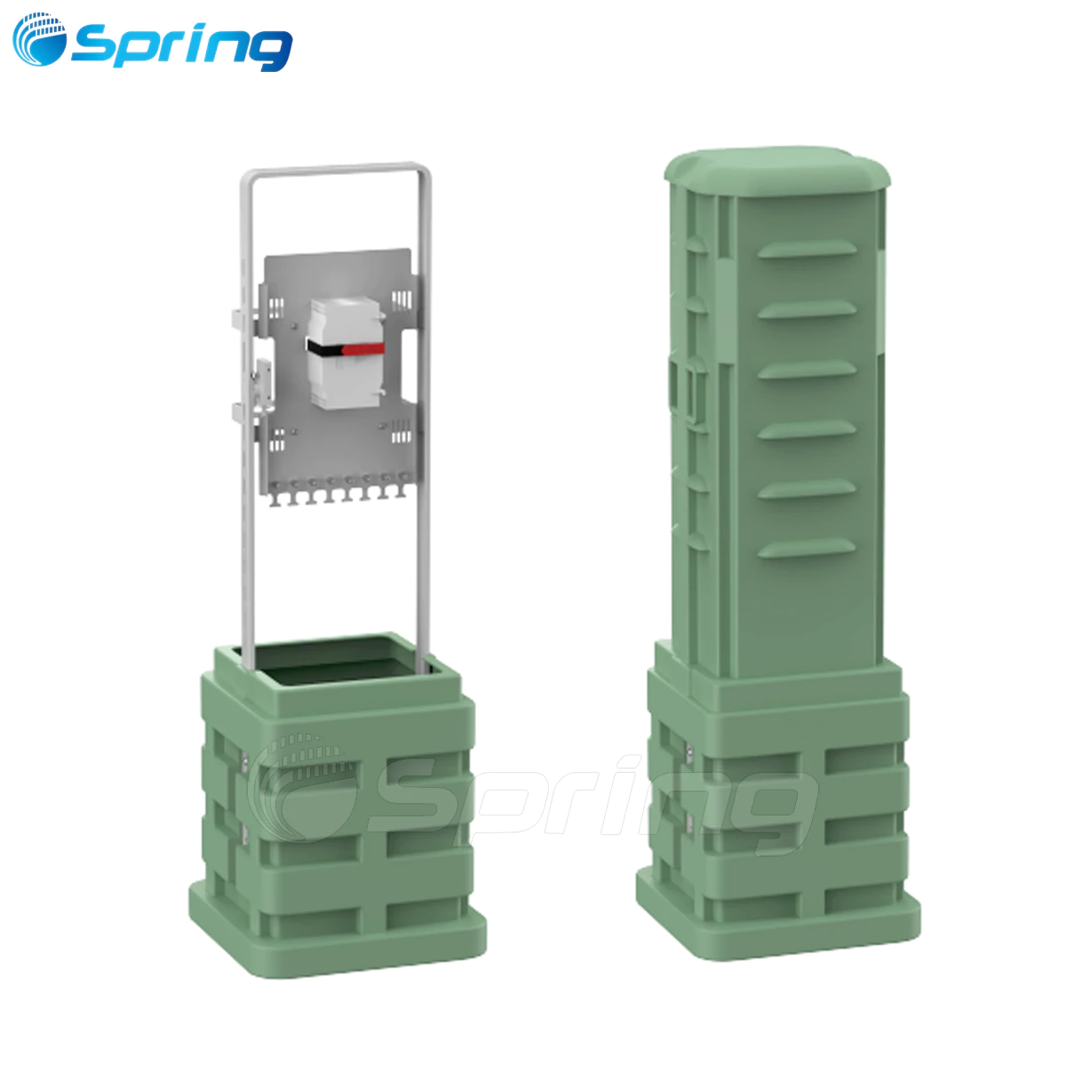
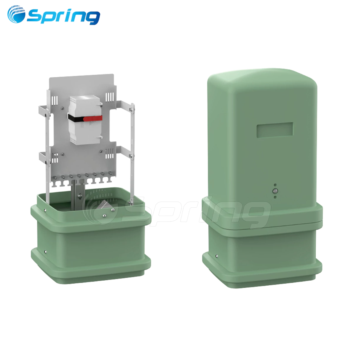
What Is a Fiber Optic Handhole?
A fiber optic handhole is also known as a fiber optic vault.It is a shallow, rectangular or square underground enclosure specifically engineered for fiber optic and telecommunications networks. Fiber Optic Handholes provide access to fiber optic cables, conduits or power lines for splicing, pulling or maintenance operations.
In contrast with manholes, Fiber Optic handholes do not typically allow personnel access - instead they serve as pull points, junctions and chambers that store cable. These vital access points serve multiple critical functions in network infrastructure.
Fiber Optic handholes are designed for underground network access, especially for fiber optical and electricity industries. Manufactured with innovated composite material, making this system an ideal solution of strong, light, flexible, time & cost saving comparing to concrete manholes.

Benefits of Fiber Optic Handholes
|
Network Expanding |
Fiber systems can be quickly extending by using the handhole access points |
|
Cost |
Avoid expensive road closures or digging by using existing handhole access. |
|
Safety |
Reduce risks of cable damage during digging or maintenance. |
|
Maintenance |
Can locate, inspect and repair quickly |
Advantages of Handholes in Fiber Optic Installation
Improved Uptime: Easy access means faster repair time during fiber outages.
Efficient Cable Routing: Ideal for micro-duct cable or blown fiber cables.
Lower Installation Costs: Especially with preformed plastic or polymer models.
Future Scalability: Makes network upgrades and expansions more efficient.
Aesthetic Appeal: Keeps infrastructure hidden and protected.
The Main Select Point of The Fiber Optic handles
|
Materials |
Size |
Load Rating |
Shape |
|
Precast Concrete |
12" x 12" x 18" |
ANSI/SCTE, Tier 15 |
Squre |
|
Polymer Concrete |
17″ x 30″ x 24″ |
ANSI/SCTE, Tier 22 |
Round |
|
HDPE (High-Density Polyethylene) |
24″ x 36″ x 24″ |
||
|
30″ x 48″ x 36″ |
Materials Used in Fiber Optic Handhole Construction
Precast Concrete: Best for heavy duty installations and high traffic areas.
Polymer Concrete: Offers high compressive strength and lighter weight compared to traditional concrete.
HDPE: Good for residential or light utility access, often used in landscaping or irrigation.
SMC: better performance than HDPE, light weight, strong, non corrosive, and excellent for telecom installations.
Fiber Optic Handhole Sizing Guide
|
Application |
Common Sizes (L x W x H) |
|
Fiber Splicing |
24″ x 36″ x 24″ |
|
Electrical Junction |
30″ x 48″ x 36″ |
|
Traffic Signals |
17″ x 30″ x 24″ |
|
Small Irrigation |
12″ x 12″ x 18″ |
HDPE/SMC Handhole Advantages Than Concrete Handholes.
|
Items |
HDPE or SMC handhole |
Concrete handhole |
|
Weight |
Light |
Heavy |
|
Installation Time |
Short |
Long |
|
Installation Cost |
Cheap |
Expensive |
|
Need tool or not |
No |
Yes |
Step-by-Step Fiber Optic Handhole Installation Guide
Handholes are an essential component in underground infrastructure systems, providing easy access for cable splicing, maintenance, and routing.
Below is a detailed step-by-step guide for proper handhole installation to ensure safety, durability, and performance.
Step 1: Site Preparation and Planning
Before excavating for the handhole, discover present subsurface lines of power, water, communication, etc. so that they can avoid being damaged.
Select the exact place to install the handhole so that it has the proper degree of accessibility, water drainage characteristics for which provision may be required by the code, expected load upon it (pedestrian traffic, light vehicular traffic and heavy traffic), the position of the entrance for the ducting.
Determine that the correct load rating and size of handhole are available for the conditions of application.
Step 2: Digging the Handhole
A hole shall be dug which is slightly larger than the handholes ordered to be placed.
Typically, the excavated hole should be three to six inches larger on each side than width and length of the box in order that it may be properly set in place as well as backfilled.
At the bottom thereof, there shall be placed from six to eight inches of well compacted gravel or crushed stone.
It will afford a better base to set the box upon. If the native soil is of a soft, wet and unstable character, foundation mud may have to be removed and replaced by a properly compacted structural fill if deemed necessary by the engineer.
Step 3: Setting the Handhole

The handhole is hoisted to the upper edge of the excavated hole and lowered thereby in a vertical position into the same so that it is not stressed unduly in any way and improperly damaged.
The box is set therein so that the upper handhole top is flush with the final ground level or slightly above to afford no opportunity for water to create undue pooling about thereon.
The entrance ducts into the handhole should be possibly housed in such a way as to enter the handhole without the necessity of bending in a manner that may cause damage not within the allowable bend radius or an adjacent structure.
The ducts should lead right into the knock out holes or port entrance in the handhole.
Step 4: Conduits or Cables

The conduit or cables should have its minimum bending radius if required for the entrance into the handhole.
The various openings into the handholes should be water-tight or rodent-proof.
The applicants may seal these various openings if necessary through cement, foam sealant or mechanical seals.
If it is desired to install a splice closure inside the box for fiber, slack storage and other space provisions should be made for possible future expansion.
Step 5: Backfill and Site Restoration

Backfill in lifts, compacting each lift to prevent settlement.
Do not operate large mechanical compactors directly over the handhole.
In roadways, or other areas where loads are heavy, provide a concrete collar or slab around the box for added strength.
Restore the surface materials (asphalt, pavers, sod, etc.) to the originally condition.
Step 6: Inspection and Maintenance
Check that cover is in a horizontal position and locked securely.
Check that drainage pathways and seals are functional.
Periodically inspect to remove debris, debris or water, cable slack and splices must not be disturbed.
During expansion plans, consider the possibility of installing a larger handhole, or leaving a certain number of conduits open for future cables.
Important Suggestions for Installation
Always choose the correct load rating as determinated by the environment (i.e., pedestrian vs. vehicular traffic).
Do not allow conduits to deflect excessively before terminating in handhole - increase pulling tension.
The base must be properly compacted to prevent box settlement or misalignment of lid.
Avoid deep pounding or handhole with heavy equipment on lid or wall.
The top edge of the handhole must be on a level plain or slightly above ground water level for drainage purposes.
Also in telecommunication applications, ground provisions must be provided along with cables routed in an orderly fashion with brackets and trays folders.
Conclusion:
The most common size of the handhole in telecom is 17 x 30 x 24"and 24 x 36 x 24", tier 15 & tier 22 base on the projects request.
If you want to do the quick installation and save the labor cost without any tools request, you can select HDPE/SMC handholes.
Contact Spring team to get your price of our excellent SMC handholes.