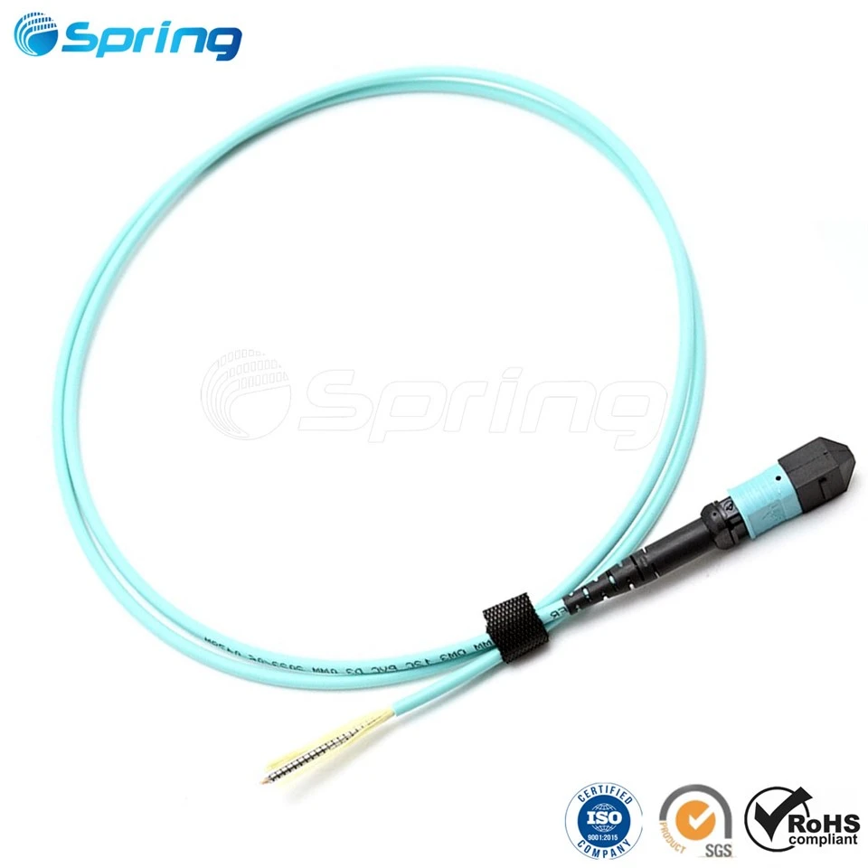


In modern optical networks, low insertion loss and high durability are critical. But what actually determines the quality and reliability of a fiber optic patch cord? It all lies in the precision of the manufacturing process.
As a leading optical equipment manufacturer, we adhere to rigorous precision standards at every stage of production-from automated cable feeding to 400× microscopic inspection. Below is a step-by-step breakdown of how high-performance fiber patch cords are built.
Key Takeaways (TL;DR):
Precision Length Control: Jacket stripping is maintained precisely at 34–36 mm to ensure structural stability.
Thermal Stripping Protection: Prevents micro-cracks on delicate 125μm glass cores.
4-Step Polishing Routine: Removes epoxy and eliminates surface defects down to ADS mirror polishing.
100% Quality Standard: Every connector meets an Insertion Loss (IL) ≤ 0.2 dB requirement with zero core defects under 400× magnification.
Step 1: Automated Cable Cutting & Component Loading


The manufacturing process begins with automated cable preparation to eliminate human error and achieve tight length tolerances.
Automatic Cable Feeding & Winding: High-speed, high-efficiency equipment ensures exact cable length with minimal error.
Pre-loading Components: Strain relief boots, crimp rings, and connector components are pre-assembled onto the cable jacket prior to stripping.
Step 2: Thermal Cable Stripping & Epoxy Application


Protecting the bare optical fiber during outer jacket removal is essential to maintain tensile strength and light transmission.
| Parameter | Specification / Standard |
| Jacket Stripping Length | Strictly controlled at 34 – 36 mm |
| Stripping Method | Thermal fiber stripping equipment |
| Quality Objective | Prevents physical scratches & micro-cracks |
Standardized Stripping: Outer jackets are removed according to exact technical templates to guarantee consistent length across batches.
Thermal Stripping Advantage: Unlike manual mechanical tools, thermal fiber stripping applies uniform heat to safely remove tight buffers without nicking the glass cladding.
Step 3: Connector Assembly & Constant-Temperature Curing


A stable glass-to-ferrule bond prevents fiber pistoning during temperature fluctuations.
353ND Premium Epoxy: We exclusively use imported 353ND epoxy, industry-recognized for its high-temperature resistance and structural integrity.
Automated Dispensing: Automated epoxy injectors fill the ceramic ferrule evenly, eliminating air pockets and voids.
Constant-Temperature Oven Curing: Connectors are cured in temperature-controlled ovens to ensure uniform heat distribution and complete epoxy polymerization.
Step 4: Precision Crimping & Assembly


Mechanically locking the aramid yarn (Kevlar) to the connector body guarantees physical durability during installation.
High-Standard Crimping: Precision crimping tools secure the outer jacket and strength members to the connector housing.
Performance Enhancement: This process dramatically improves mating durability, strain relief, and maximum tensile strength under heavy pulling loads.
Step 5: The 4-Step End-Face Polishing Process


Optical performance depends entirely on the cleanliness and geometry of the ferrule end-face. We utilize a strict 4-step layer-by-layer polishing routine:
[Step 1: 30μm Epoxy Removal] ➔ [Step 2: 9μm Rough Polishing] ➔ [Step 3: 1μm Fine Polishing] ➔ [Step 4: ADS Mirror Polishing]
30μm Removal: Safely removes excess cured epoxy stub from the ferrule tip.
9μm Rough Polishing: Shapes the ceramic ferrule radius and removes major surface marks.
1μm Fine Polishing: Smoothes surface roughness and readies the ferrule for final finishing.
ADS Mirror Polishing: Creates an ultra-smooth, scratch-free mirror finish to minimize light reflection.
Step 6: 100% Inspection & Optical Performance Testing


Zero-defect manufacturing requires rigorous testing on every single patch cord before it leaves the production floor.
100% Insertion Loss (IL) Testing: Every connector must achieve IL ≤ 0.2 dB to comply with Grade-A transmission efficiency.
400× CCD Microscope Inspection: Connectors are inspected visually under high-power microscopes.
Core Zone Quality: We ensure zero defects, scratches, or contamination within the critical 125μm fiber core area.
Step 7: Final Packaging & Quality Certification
Once quality checks are complete, each cable is documented and packaged for safe global shipping.
Certificate of Quality: An official QC compliance card is included with approved batches.
Protective Packaging: Connectors are capped with dust covers and individually sealed to protect end-faces during transit.
Looking for Reliable, High-Precision Fiber Patch Cords?
From automated assembly to Grade-A end-face polishing, our factory delivers OEM optical connectivity built for mission-critical networks.
📩 [Contact Our Engineering Team] today for custom specifications, test reports, or wholesale quotes!