Introduction
Installing a fiber optic patch cable may seem straightforward, but proper installation requires much more than simply connecting two optical ports.
Without standardized routing practices, patch cables can quickly become disorganized, making future maintenance difficult, increasing troubleshooting time, and even affecting network reliability. A well-planned installation not only keeps fiber infrastructure neat and organized but also improves operational efficiency throughout the network's lifecycle.
This guide explains what a fiber optic patch cable is, how it is classified, the essential routing standards for proper installation, and the complete installation process used in telecommunications networks, FTTH deployments, and data centers.
What Is a Fiber Optic Patch Cable?

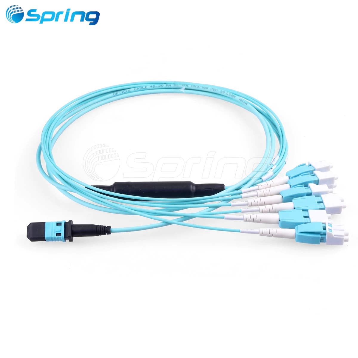
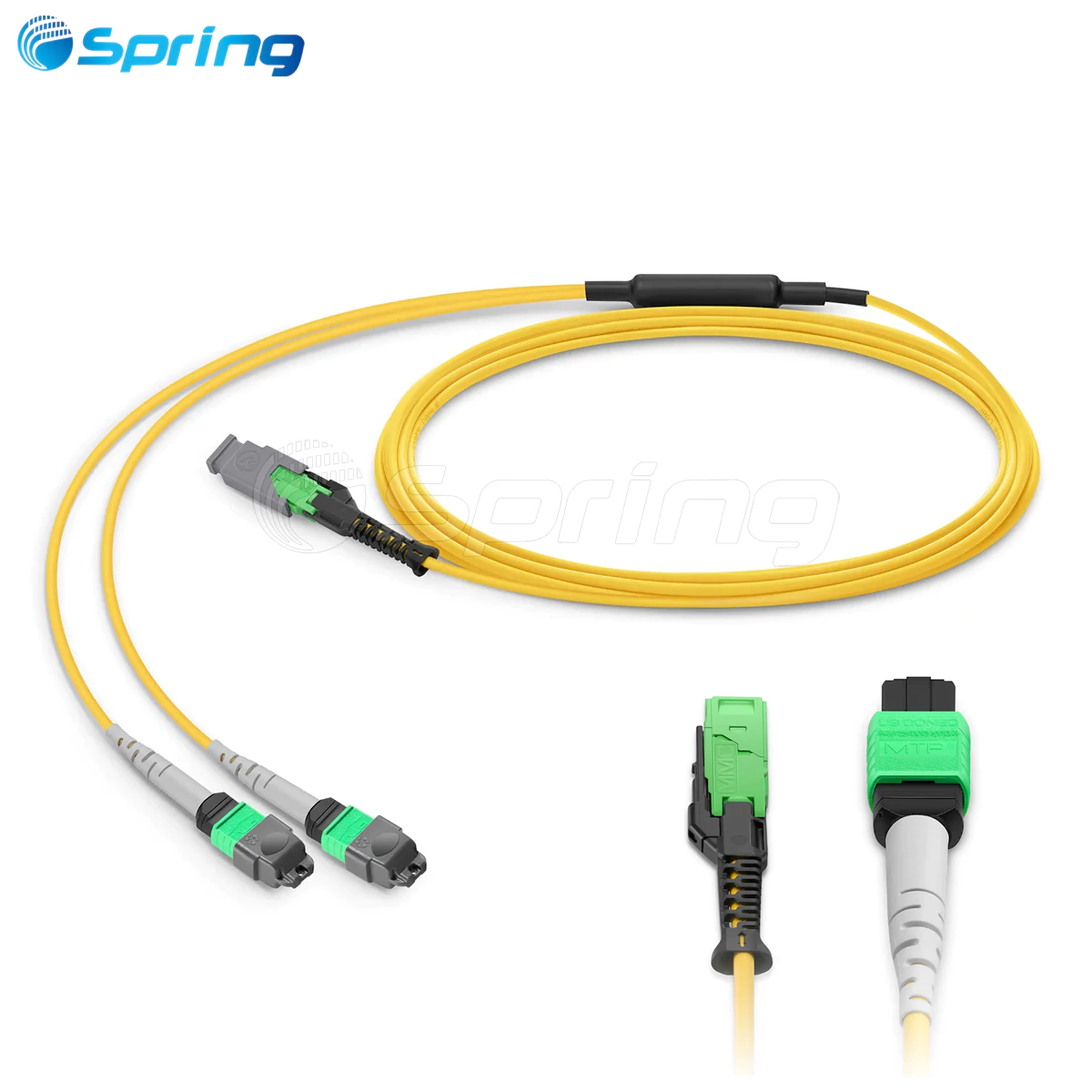
A fiber optic patch cable, also known as a fiber patch cord or fiber jumper, is a factory-terminated optical cable used to establish connections between optical communication equipment.
Fiber optic patch cables are commonly used in the following three scenarios:
Connecting one network device to another.
Connecting network equipment to an Optical Distribution Frame (ODF).
Connecting one Optical Distribution Frame (ODF) to another ODF.
Because fiber patch cables are frequently installed, removed, and reconfigured during network operation, proper routing and cable management are essential for maintaining a reliable and organized fiber network.
Types of Fiber Optic Patch Cables


Fiber optic patch cables can be classified according to connector type, cable length, and application.
Classification by Connector Type
FC Fiber Optic Connector
The FC connector features a threaded metal coupling mechanism that provides a secure and vibration-resistant connection.
It is most commonly used on the ODF side of optical communication systems.
Typical application:
Optical Distribution Frame (ODF)
SC Fiber Optic Connector
The SC connector uses a square-shaped housing with a push-pull locking mechanism.
It is widely used with GBIC optical modules and requires no rotation during installation.
Typical applications include:
Routers
Ethernet switches
PON equipment
ST Fiber Optic Connector
The ST connector uses a bayonet-style locking mechanism with a round housing.
Although less common today, it is still found in traditional fiber distribution systems.
Typical application:
Optical Distribution Frame (ODF)
LC Fiber Optic Connector
The LC connector is designed for SFP optical modules and features a compact modular latch mechanism.
Its small form factor makes it ideal for high-density networking equipment.
Typical applications include:
Routers
Ethernet switches
SFP optical modules
Classification by Cable Length
Common standard lengths include:
1.5 m, 2 m, 3 m, 5 m, 10 m, 15 m, 20 m
Custom cable lengths are also available to meet specific installation requirements.
Classification by Application
Different connector types are commonly selected according to the application.
LC connectors are typically used for equipment-to-equipment connections.
FC connectors are commonly used for ODF terminations and remote fiber connections.
SC connectors are widely used between ODFs and active network equipment.
Fiber Optic Patch Cable Routing Standards
Modern optical communication equipment typically features high-density fiber interfaces. Without standardized routing practices, fiber patch cables can quickly become tangled, creating a "spaghetti cabling" environment that significantly increases maintenance difficulty.
To ensure a clean, organized, and serviceable fiber infrastructure, the following routing standards should be followed.
1. Keep Cable Routing Organized
Fiber patch cables should always be routed neatly inside:
Optical Distribution Frames (ODFs)
Fiber Distribution Cabinets
Telecommunications Cabinets
Cable routing should remain:
Organized
Easy to identify
Convenient for maintenance
Space-efficient
2. Control Excess Cable Length
The remaining slack of each fiber patch cable should generally be controlled within approximately 500 mm.
Excessive slack creates congestion, while cables that are too short place unnecessary tension on connectors.
3. Never Use Patch Cables That Are Too Short
Patch cables that cannot comfortably reach the destination should not be used.
Connecting two patch cables with a fiber optic adapter is not recommended because it introduces additional insertion loss.
4. Maintain Proper Bend Radius

Each fiber patch cable should maintain an adequate bend radius throughout the installation.
Sharp bends should always be avoided to prevent optical signal loss and fiber damage.
5. Follow the Correct Connection Sequence

When installing a patch cable:
Connect one end to the equipment port.
Route the cable through the designated cable management channel.
Pull out the fiber management tray.
Coil the excess cable neatly.
Secure the cable using a hook-and-loop fiber cable tie.
Return the tray to its original position.
Connect the opposite end to the destination equipment or ODF.
6. Follow Standard Cable Routing Practices
General routing requirements include:
Route overhead fibers down along the outside of the ODF.
Select the most suitable fiber storage post based on the amount of excess cable.
Route the cable upward along the inside of the ODF.
Follow the designated horizontal and vertical cable management paths.
Each patch cable should:
Pass along the outside of the ODF only once.
Pass along the inside of the ODF only once.
Use only one designated fiber storage post.
Do not wrap, cross, or suspend fibers between multiple storage posts.
Organize all patch cables before securing them with cable ties.
All patch cables should remain inside the ODF.
Unsupported routing or "flying fibers" should be strictly avoided.
Emergency spare patch cables should also be stored properly without affecting future maintenance.
7. Do Not Cross Multiple Fiber Management Trays
The same patch cable should never be wrapped across multiple fiber storage trays.
8. Protect Fibers Between Equipment Cabinets

When patch cables pass between equipment cabinets, protective tubing should be used to prevent the fiber from being crushed by other cables.
Whenever possible, cables should remain inside the cable management system.
9. Avoid Excessive Cable Tension

Fiber patch cables should never be stretched tightly.
Connectors should also never be subjected to sharp right-angle bends.
10. Route All Fibers Inside Cable Management Channels

Every fiber patch cable should remain inside designated cable trays or cable routing channels.
External routing or unsupported flying fibers should never occur.
11. Never Join Two Fiber Patch Cables

If a cable is too short, replace it with a longer one.
Joining two patch cables with a fiber optic adapter increases insertion loss and should be avoided.
12. Clean Fiber Connectors Before Installation
Before inserting a connector:
Remove the dust cap.
Clean the fiber end face.
Never touch the polished end face with your fingers.
Prevent the connector from contacting dust or contaminated surfaces.
13. Insert Fiber Connectors Correctly

Always insert fiber connectors vertically into the optical port.
Avoid inserting connectors at an angle.
Ensure the connector is fully seated.
For SC and LC connectors, an audible "click" typically indicates that the connector has locked into position.
14. Never Pull on the Fiber Cable

Excessive pulling force may damage both the connector and the optical fiber.
15. Avoid Twisting Fiber Cables

Fiber patch cables should remain naturally relaxed during installation.
Twisting the cable can damage the fiber and shorten its service life.
Fiber Optic Patch Cable Installation Process
After understanding the routing standards, the next step is the actual installation.
A standard fiber optic patch cable installation consists of six steps.
Step 1 – Preparation
Prepare all required tools, materials, and site information before beginning the installation.
Tools
Permanent marker
Protective tubing
Cable labels
Oil-based marker
Notebook
Pliers
Electrical tape
Materials
Fiber optic patch cables
Optical transceivers
Hook-and-loop fiber cable ties
Prepare the required quantities, connector types, and cable lengths according to project requirements.
Before installation, record the locations of:
Equipment cabinets
Equipment ports
Optical Distribution Frames (ODFs)
Equipment room layout
Using different colored cable ties can help distinguish different types of fiber connections.
Step 2 – Select the Appropriate Patch Cable
Select the correct patch cable according to:
Connector type
Cable length
Equipment interface
Optical splitter
Fiber distribution box adapter
The recommended excess cable length should be controlled within 50 cm.
Step 3 – Route the Fiber
Install the patch cable according to the routing standards described above.
The installation procedure includes:
Confirm the location of the equipment, optical splitter, or fiber distribution box.
Remove the dust cap from the connector.
Connect one end of the patch cable to the corresponding equipment.
Route the cable through the designated cable pathway.
Connect the opposite end to the destination equipment.
Step 4 – Apply Cable Labels

Proper labeling greatly improves future maintenance efficiency.
Attach a printed label approximately 1–2 cm behind each connector at both ends of every patch cable.
Recommended labeling practices include:
Use machine-printed labels instead of handwritten labels.
When installing multiple patch cables simultaneously, temporarily identify each cable before applying permanent labels.
Label both ends of every patch cable.
Maintain a consistent label orientation.
For vertical cables, labels generally face left.
For horizontal cables, labels generally face downward.
Step 5 – Bundle the Fiber

Secure patch cables using hook-and-loop fiber cable ties at regular intervals.
Recommended practices include:
Maintain approximately 20 cm spacing between cable ties.
Install cable ties on both sides of cable bends.
Maintain a minimum bend radius of 30 mm for 2 mm cables.
Maintain a minimum bend radius of 40 mm for 3 mm cables.
Ensure the soft side of the cable tie contacts the fiber cable.
Do not allow the hook surface to contact the cable jacket directly.
Straighten cables before bundling.
Do not overtighten cable ties.
Minimize cable crossings whenever possible.
Step 6 – Final Inspection and Cleanup
After completing the installation:
Return all tools to their designated storage locations.
Collect unused materials.
Clean the work area.
Submit the installation report to the responsible personnel.
If the network is already operational, notify the operations and maintenance team that fiber patching has been completed.
Conclusion
Proper fiber optic patch cable installation not only creates a clean and organized cabling environment but also significantly improves network operation and maintenance.
Well-managed fiber routing makes it easier to identify individual fibers, simplifies troubleshooting, reduces maintenance time, and improves the long-term reliability of the optical network.
Whether working in an FTTH network, a telecommunications central office, or a data center, following standardized routing practices and installation procedures is essential for building a reliable, efficient, and easy-to-maintain fiber infrastructure.