Introduction
Fiber optic networks are designed to deliver exceptional bandwidth, ultra-low latency, and reliable long-distance communication. Whether supporting FTTH broadband, GPON/XGS-PON networks, enterprise LANs, hyperscale data centers, 5G fronthaul, or industrial automation, fiber optics has become the backbone of modern digital infrastructure.
However, even the most advanced fiber network can experience one frustrating problem: unexpected signal loss.
A connection that once operated flawlessly may suddenly suffer from slow speeds, intermittent disconnections, increased packet loss, or complete service outages. For network operators, Internet Service Providers (ISPs), contractors, and field technicians, identifying the root cause quickly is essential to minimizing downtime and avoiding expensive maintenance costs.
Fiber signal loss-also known as optical attenuation-is a normal physical phenomenon. Every connector, splice, splitter, and meter of optical fiber introduces a small amount of loss. Problems arise when the accumulated loss exceeds the network's allowable optical power budget, causing the receiver to receive insufficient optical power for stable communication.
Unfortunately, signal degradation is rarely caused by a single factor. It is often the result of multiple issues working together, including contaminated connectors, excessive bending, poor splicing, mechanical stress, moisture ingress, damaged cables, incorrect installation practices, or low-quality passive components.
Many fiber troubleshooting guides simply list common problems without explaining why they happen, how to identify them, and how to prevent them in future installations. This guide takes a more practical approach. Instead of only describing the symptoms, we will explain the engineering principles behind fiber optic signal loss, provide a systematic troubleshooting workflow, and share field-proven best practices used in real FTTH and data center deployments.
Quick Summary / Key Takeaways:
Optical attenuation (signal loss) becomes critical when it exceeds your network's specific optical power budget.
Microscopic contamination on fiber connector end faces remains the number one cause of network failures.
Physical macro-bending and micro-bending leak light out of the fiber core, which can be mitigated by using high-quality G.657 bend-insensitive fiber.
Outdoor deployments require ruggedized, IP68-rated hardened solutions to prevent moisture ingress and signal degradation over time.
Following a structured troubleshooting workflow with OTDR testing and optical power meters prevents unnecessary component replacement and speeds up restoration.

What Is Fiber Optic Signal Loss?
Fiber optic signal loss, commonly called fiber attenuation, refers to the reduction of optical power as light travels through an optical fiber. Unlike electrical cables that lose energy through resistance, fiber optics experience loss because light interacts with the fiber material and every component in the optical link.
A typical optical link includes multiple elements:
Optical Line Terminal (OLT)
Backbone fiber cable
Fusion splices
Distribution cables
Multiport Service Terminals (MST)
Connectors
Optical Network Terminal (ONT)
Each component contributes a small amount of attenuation. When properly designed, the total loss remains within the allowable optical budget specified by the equipment manufacturer. When total attenuation exceeds that budget, communication becomes unstable or fails entirely.
Signal loss generally falls into two categories:
1. Insertion Loss (IL)
Insertion Loss measures how much optical power is lost while the signal passes through a connector, splice, splitter, or other passive component. Typical sources include dirty connector end faces, poor connector alignment, low-quality adapters, fusion splice defects, excessive fiber bending, or damaged optical cables. For most modern FTTH networks, maintaining low insertion loss is essential for ensuring reliable downstream and upstream transmission. Typically, a high-quality single-mode connector should exhibit a high insertion loss if it goes above the standard threshold of 0.3 dB.
2. Return Loss (RL)
Return Loss measures the amount of reflected optical power traveling back toward the transmitter. Unlike insertion loss, which weakens the transmitted signal, high reflection interferes with laser performance and may cause unstable communication. Common causes include poor connector polishing, connector contamination, air gaps, improper APC/UPC connections, or damaged ferrules. High-performance FTTH systems typically require Angled Physical Contact (APC) connectors to maximize return loss (reducing optical reflection) and improve long-distance transmission stability.
Symptoms of Fiber Signal Loss
Fiber problems rarely appear without warning. Before a complete network outage occurs, technicians often observe several performance indicators.
Slow Internet Speed: Customers frequently complain that download speeds have dropped significantly despite having no apparent equipment failure. This is often one of the earliest signs of excessive attenuation.
Intermittent Connection: The connection repeatedly disconnects and reconnects. These intermittent failures usually indicate unstable optical power rather than complete fiber breaks.
Increased Packet Loss: Applications requiring real-time communication-including video conferencing, IPTV, cloud services, and VoIP-may experience dropped packets caused by unstable optical signals.
High Bit Error Rate (BER): Enterprise networks and data centers may detect increasing transmission errors before users notice service degradation. Monitoring BER provides an early indication of optical link deterioration.
Optical Power Alarm: Many GPON, XGS-PON, and enterprise switches continuously monitor received optical power. If the received power falls below the receiver sensitivity threshold, alarm notifications are triggered automatically.
Complete Signal Failure: In severe cases, communication stops entirely. Typical causes include a broken fiber, severely contaminated connectors, major cable damage, incorrect patching, or failed passive components. At this stage, professional diagnostic tools such as an OTDR testing unit and an Optical Power Meter are required to identify the fault location accurately.
12 Common Causes of Fiber Optic Signal Loss
1. Dirty Fiber Connectors

Industry studies consistently show that contaminated connector end faces are among the leading causes of fiber network failures. Dust particles invisible to the naked eye can block or scatter the optical signal, increasing high insertion loss and degrading return loss. Even microscopic contaminants such as fingerprints, skin oils, or airborne dust can significantly affect optical performance, especially in high-speed GPON, XGS-PON, and 400G/800G data center links. Outdoor FTTH installations are particularly vulnerable because connectors may be exposed to moisture, construction dust, and repeated field connections.
Common Symptoms: Unstable optical power, increased insertion loss, high return loss, intermittent service interruptions, and failed OTDR acceptance tests.
Recommended Solutions: Implement strict fiber connector cleaning protocols. Inspect every connector with a fiber microscope before mating. Clean connector end faces using a professional fiber cleaning pen or lint-free wipes with isopropyl alcohol. Always install dust caps immediately after disconnecting. Never touch the ferrule end face with your fingers, and replace connectors showing permanent scratches or pits.
2. Excessive Fiber Bending (Macro-Bending and Micro-Bending)

Optical fibers are engineered to guide light efficiently through the fiber core. However, when the cable is bent beyond its minimum bend radius, part of the optical signal escapes into the cladding, resulting in fiber attenuation. There are two primary types of bending loss:
Macro-bending: Large, visible bends caused by improper routing or tight cable management inside splice trays and cabinets.
Micro-bending: Tiny, often invisible deformations caused by excessive localized cable pressure, improper fastening, or manufacturing defects.
Recommended Solutions: Follow the manufacturer's minimum bend radius specifications (typically 20 times the cable diameter during installation and 10 times during operation). Avoid tightly coiling excess cable and never secure fiber cables with overly tight cable ties. For tight routing spaces, deploying cables with G.657.A2 bend-insensitive fiber ensures maximum bend tolerance and minimal signal leakage.
3. Poor Fusion Splicing
Fusion splicing permanently joins two optical fibers with minimal loss. However, improper splicing remains a common cause of excessive attenuation in FTTH deployments. Splice loss may result from fiber core misalignment, dirty fiber ends, an incorrect cleaving angle, air gaps, or poor splice protection. Even a splice that initially passes testing may become unstable if mechanical stress develops inside the tray over time.
Common Symptoms: High insertion loss localized to a specific distance, distinct OTDR reflection events, or reduced optical power downstream.
Recommended Solutions: Use high-precision core-alignment fusion splicers. Ensure proper fiber cleaving and clean fibers thoroughly before splicing. Protect every splice with a heat-shrink sleeve and always verify the final splice quality using OTDR testing to ensure the loss is under the standard 0.1 dB threshold.
4. Damaged Fiber Cables
Physical damage is often the most obvious source of signal loss. Fiber cables may become damaged by construction equipment (backhoe fade), rodents, crushing forces, excessive pulling tension during installation, vehicle traffic over temporary lines, or improper storage. Damage may affect only part of the fiber core or cladding, causing intermittent failures long before a complete cable breakage occurs.
Recommended Solutions: Perform visual inspections of the cable path. Use an OTDR testing routine to accurately locate the exact distance of the damaged section. Replace severely compressed or kinked cable segments. For harsh environments, always specify armored fiber cables or protect underground installations with heavy-duty conduits and handholes.
5. Connector Mismatch
Not every fiber connector is compatible with one another, and mating mismatched types can cause severe optical degradation. A frequent field error is mating an APC (Angled Physical Contact, green) connector with a UPC (Ultra Physical Contact, blue) connector. Because the APC ferrule is polished at an 8-degree angle and the UPC ferrule is flat, mating them creates a physical air gap, resulting in extremely high insertion loss and terrible return loss.
Recommended Solutions: Verify connector type and color-coding before installation. Clearly label patch panels and adapter plates. Never mate APC connectors with UPC connectors unless using a hybrid patch cord specifically designed for that purpose. Use high-quality adapters with ceramic alignment sleeves to ensure precise physical alignment.
6. Low-Quality Fiber Components
Reducing initial material costs by selecting low-quality passive components often increases long-term troubleshooting and maintenance expenses. Poor-quality components typically exhibit higher factory insertion loss, inferior ferrule polishing, weak environmental sealing, and a shorter service life under extreme temperatures. This applies to connectors, adapters, PLC splitters, drop cables, patch cords, and splice closures.
Recommended Solutions: Partner with certified manufacturers who provide verifiable test reports for every batch. Investing in carrier-grade passive components, such as premium PLC splitters, Multiport Service Terminals, and factory-terminated patch cords, significantly improves network reliability and eliminates mystery signal drops.
7. Moisture and Water Ingress

Outdoor fiber networks frequently operate in harsh environments where moisture becomes a major threat to optical stability. If water enters standard splice closures, fiber distribution boxes, or unsealed connectors, it can cause increased attenuation, connector contamination, and long-term component degradation. In colder climates, trapped water freezes and expands, causing severe micro-bending loss or completely crushing the glass fiber.
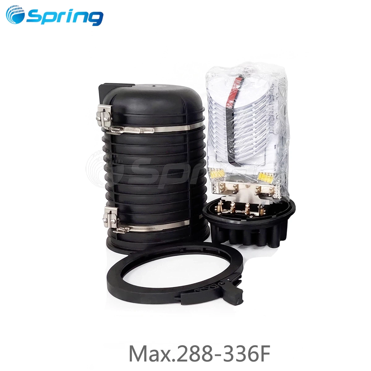
Recommended Solutions: For outdoor OSP (Outside Plant) deployments, utilize IP68-rated hardened connectors and Multiport Service Terminals (MST) to provide robust, water-tight seals. Inspect rubber gaskets regularly during routine maintenance and replace any damaged sealing components immediately.
8. Excessive Cable Tension
Fiber optic cables are designed with strict maximum pulling loads. Exceeding these tensile limits during long cable pulls or aerial installations can stretch the cable structure, creating microscopic cracks inside the glass fiber core. Unlike complete breaks, these tensile defects may not fail immediately; instead, they manifest as gradually increasing signal loss months after the installation is completed.
Recommended Solutions: Never exceed the manufacturer's maximum tensile ratings. Use proper cable pulling equipment, such as tension-limiting winches, breakaway swivels, and cable lubricants. Always use pulling grips attached to the cable's strength members rather than pulling the connectors or the outer jacket directly.
9. Incorrect Cable Routing
Poor cable routing inside data center racks, central offices, or fiber distribution hubs is a hidden source of long-term maintenance problems. Common routing mistakes include dragging cables over sharp cabinet corners, overfilling conduits past their 40% capacity limit, leaving vertical cable runs unsupported (causing excessive self-weight tension), and poor slack management that leads to tangled cabling.
Recommended Solutions: Use dedicated vertical and horizontal cable managers, slack storage baskets, and radius-limiting routing accessories. Proper routing not only reduces immediate attenuation but also simplifies future maintenance and troubleshooting without risking adjacent live circuits.
10. Environmental Aging
Although optical fiber has an extremely long service life, years of continuous environmental exposure gradually affect cable performance. Outside plant cables are subjected to UV radiation, extreme temperature cycling, chemical exposure in underground ducts, salt spray in coastal areas, and wind-induced vibration on aerial spans, all of which can degrade the outer protective jackets over time.
Recommended Solutions: Conduct regular physical inspections of aerial and underground plant routes. Utilize cables with UV-resistant polyethylene (PE) jackets for outdoor applications and heavy-duty rodent-resistant designs where necessary. Monitor older fiber routes for historical optical power trends to catch aging infrastructure before it fails.
11. Improper Testing Procedures
Many installation and attenuation issues remain undetected during commissioning because insufficient or incorrect testing procedures were performed. Relying solely on a basic continuity test (like a red light pointer) can show that light passes through, but it will completely fail to detect high insertion loss or out-of-spec return loss that causes high bit error rates in active equipment.
Recommended Solutions: Enforce strict baseline testing protocols before network acceptance. Technicians should use a calibrated Optical Power Meter (OPM) and Light Source to measure total link loss, paired with detailed OTDR testing to map individual event losses and reflections along the entire span.
12. Inadequate Preventive Maintenance
Many network operators follow a reactive maintenance strategy, only responding after a customer opens a ticket or a complete service failure occurs. This approach leads to extended downtime and high emergency repair costs. Without routine checking, slow-growing issues like dust accumulation, loose adapters, or shifting cables will eventually cross the operating threshold unexpectedly.
Recommended Solutions: Establish a proactive maintenance framework. This includes scheduled fiber connector cleaning during modifications, continuous optical power trend monitoring via network management software, periodic OTDR testing on critical backbones, and physical cabinet inspections to ensure environmental seals remain intact.
Need reliable components for your FTTH or data center deployment? Spring Optical offers a full series of carrier-grade Multiport Service Terminals (MST), IP68 hardened drop cables, premium PLC splitters, and customized fiber assemblies engineered to minimize network signal loss.
Contact our technical team today to discuss your project requirements and receive a free quote.
A Step-by-Step Fiber Troubleshooting Workflow

When signal loss occurs, technicians should follow a structured diagnostic process rather than replacing components randomly. The following workflow outlines the systematic actions and tools required to resolve fiber troubleshooting scenarios efficiently.
Step 1 Action: Verify optical power levels Recommended Tool: Optical Power Meter (OPM) Expected Outcome / Standard: Confirm if the received optical power falls within the active equipment's working sensitivity range.
Step 2 Action: Inspect connector end faces Recommended Tool: Fiber Inspection Microscope Expected Outcome / Standard: Check for scratches, pits, dust, or oil contaminants on the ferrule end face before cleaning.
Step 3 Action: Clean all connectors Recommended Tool: Fiber Cleaning Pen / Lint-free wipes Expected Outcome / Standard: Complete professional fiber connector cleaning to ensure a perfectly clean end face with zero contamination before re-mating.
Step 4 Action: Test continuity and macro-bends Recommended Tool: Visual Fault Locator (VFL) Expected Outcome / Standard: Locate visible red light leakage caused by severe macro-bending or immediate fiber breaks near patch panels.
Step 5 Action: Locate hidden faults and events Recommended Tool: OTDR (Optical Time Domain Reflectometer) Expected Outcome / Standard: Run an OTDR testing session to pinpoint the exact physical distance of high attenuation events, micro-bends, or mid-span cable damage.
Step 6 Action: Check splice and splice tray quality Recommended Tool: Fusion Splicer + OTDR Expected Outcome / Standard: Re-splice any joints displaying a localized insertion loss greater than 0.1 dB.
Step 7 Action: Inspect routing and bend radius Recommended Tool: Visual Inspection Expected Outcome / Standard: Ensure all patch cords and buffer tubes comply with the minimum bend radius without compression.
Step 8 Action: Replace defective components Recommended Tool: Certified Fiber Components Expected Outcome / Standard: Replace low-quality or physically damaged splitters, patch cords, and adapters with certified replacements.
Best Practices to Prevent Future Signal Loss
Successful fiber networks rely on prevention rather than repeated emergency repairs. Consider the following field-proven best practices during your network design and deployment phases:
Always use certified, carrier-grade fiber optic components from trusted manufacturers.
Enforce a strict "Inspect, Clean, Inspect" policy for every single connector before it is mated.
Maintain proper bend radius controls inside all splice closures, termination boxes, and rack managers.
Perform comprehensive OTDR testing and document baseline loss measurements before final network acceptance.
Deploy IP68-rated outdoor connectors and Multiport Service Terminals (MST) in harsh environmental conditions.
Train field installers and subcontractors on modern industry standards, including correct cable pulling and cleaving techniques.
Schedule periodic maintenance inspections and track optical power levels to catch degradation early.
Frequently Asked Questions
What causes signal loss in fiber optic cables?
The most common causes include dirty connector end faces, excessive macro or micro-bending, poor quality fusion splicing, physical cable damage, connector mismatch (such as APC to UPC), and water ingress in outdoor enclosures.
Can dirty connectors really affect network performance?
Yes, absolutely. Microscopic dust particles, oils, or fingerprints on a ferrule end face can block, scatter, or reflect the laser signal. This increases insertion loss and degrades return loss, directly leading to packet drops, high bit error rates, and intermittent connectivity.
What is an acceptable insertion loss standard?
Acceptable loss values depend on your specific network design and application standards. Generally, a high-quality single-mode connector should have an insertion loss below 0.3 dB, a professional fusion splice should be below 0.1 dB, and a standard 1x8 PLC splitter will introduce around 10.5 dB of insertion loss.
What tools are mandatory for fiber troubleshooting?
Professional field technicians require an Optical Power Meter (OPM) and stabilized light source to measure total loss, an OTDR to map out faults over distance, a Visual Fault Locator (VFL) for short-distance continuity tracking, a fiber inspection microscope, and specialized tools for fiber connector cleaning.
How often should fiber connectors be cleaned?
Fiber connectors should be inspected and cleaned every single time they are disconnected and reconnected. Never assume a new patch cord out of the bag is perfectly clean; always inspect it before insertion into an adapter.
Conclusion
Fiber optic signal loss is an unavoidable characteristic of every optical network, but excessive attenuation is almost always preventable. Understanding the relationship between insertion loss, return loss, cable routing, connector cleanliness, splicing quality, and environmental conditions allows technicians to diagnose problems more efficiently and design more reliable fiber infrastructures.
Rather than treating every outage as an isolated incident, network operators should adopt a systematic approach that combines proper installation practices, high-quality passive components, routine inspection, and preventive maintenance. This not only minimizes downtime but also extends the service life of the entire optical network.
Whether you are deploying a new FTTH network, upgrading an enterprise backbone, or maintaining an outdoor fiber distribution system, following the best practices outlined in this guide will help reduce troubleshooting time, improve network performance, and lower long-term operating costs.
Spring Optical provides a comprehensive portfolio of high-performance fiber optic connectivity solutions, including pre-terminated FTTH drop cables, Multiport Service Terminals (MST), hardened connectors, splice closures, fiber distribution boxes, patch cords, PLC splitters, and customized OEM/ODM fiber assemblies. By combining quality components with proper installation and maintenance, network operators can build optical infrastructures that deliver reliable performance for years to come.