

Quick Summary & Key Takeaways
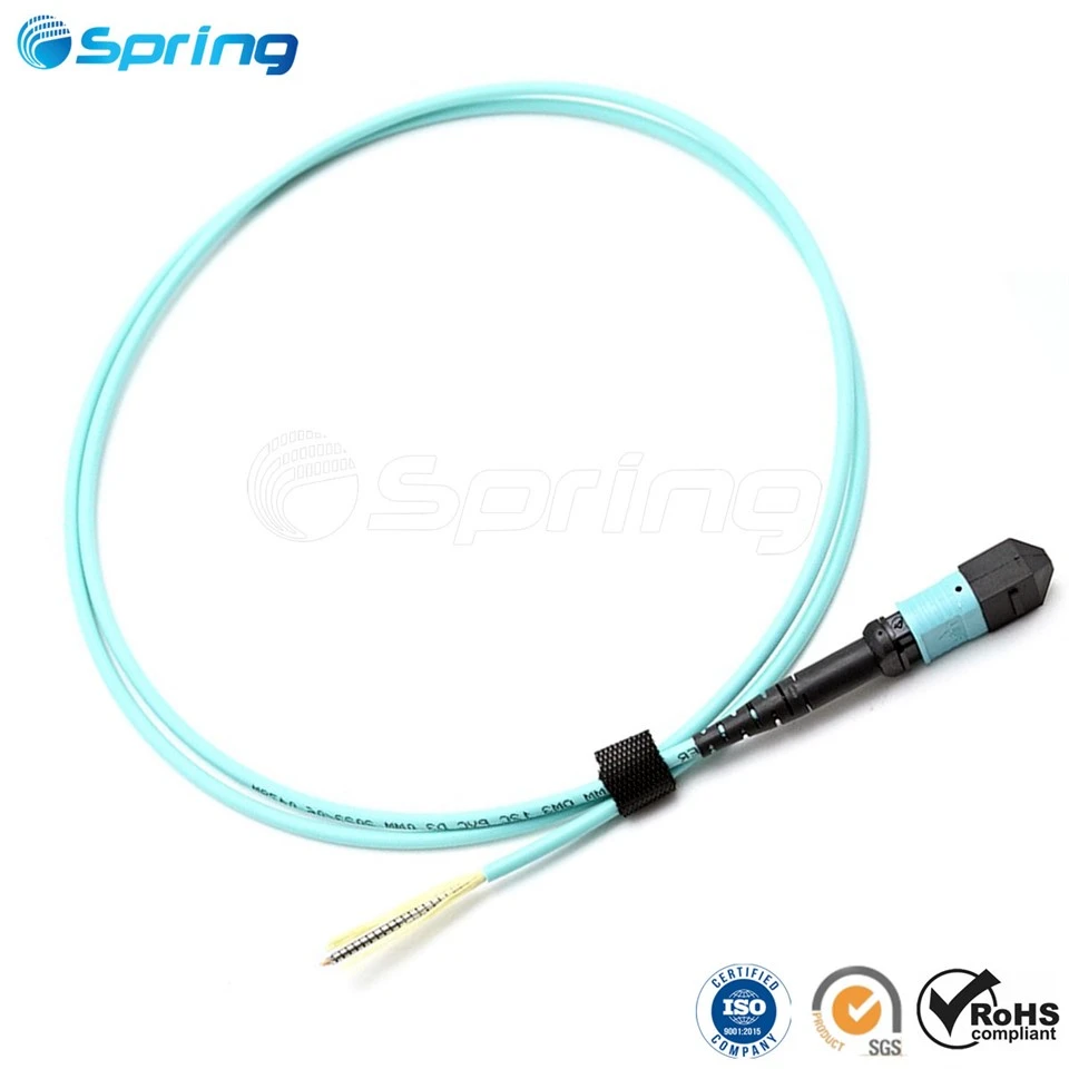
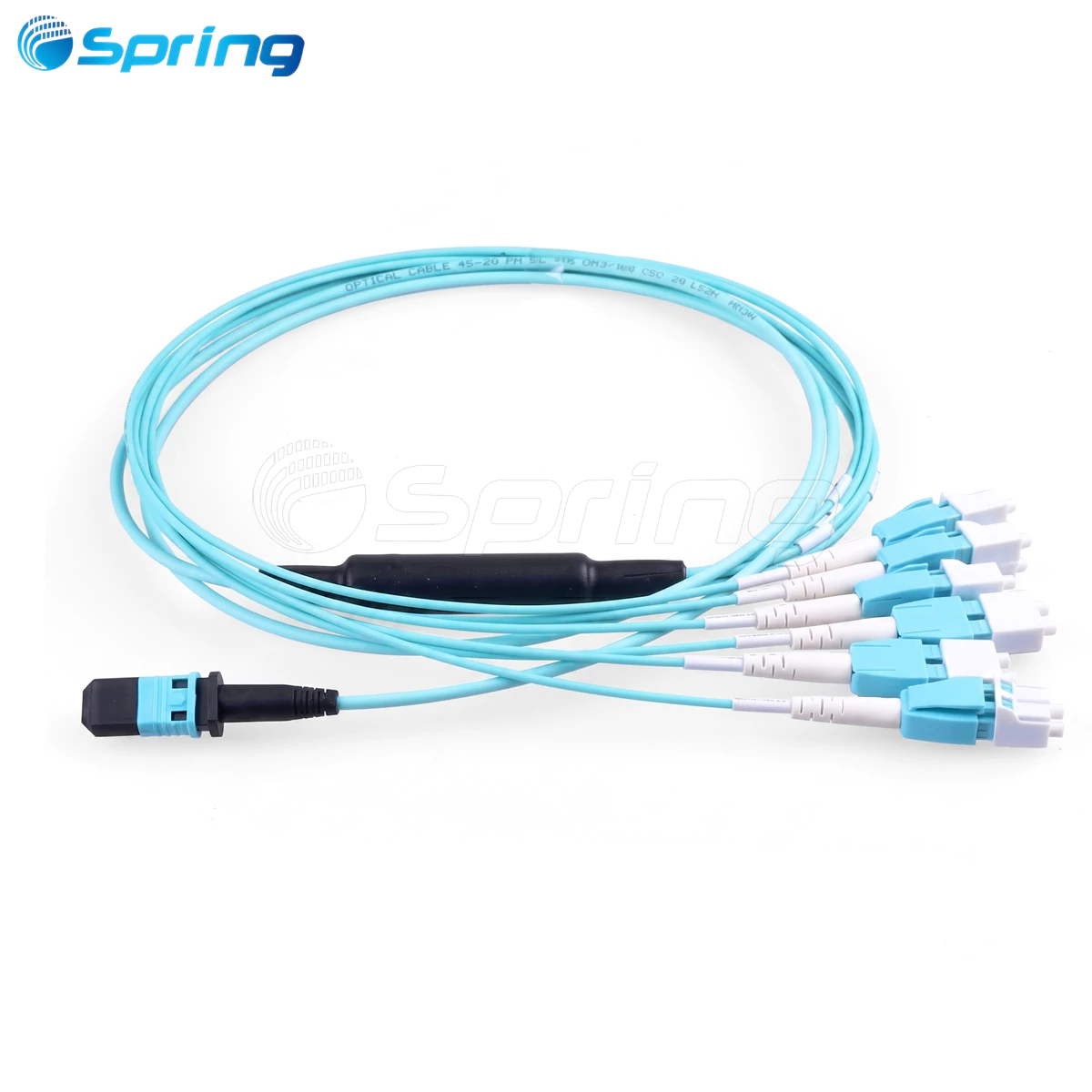
An MPO(F) to LC/UPC 8-fiber OM3 breakout cable splits a single 12-fiber MPO connector (utilizing 8 active fibers: 1–4 and 9–12) into 4 duplex LC channels. Utilizing Type-B (reversed) polarity, it enables seamless, high-density connection between 40G (QSFP+) or 100G (QSFP28 SR4) transceivers and 10G/25G equipment without requiring additional polarity correction modules.
With the rapid growth of high-speed data center networks, traditional duplex fiber cabling is increasingly being replaced by high-density parallel optical solutions.
An MPO to LC breakout cable provides an efficient way to convert a single multi-fiber MPO connection into multiple independent LC channels, enabling flexible migration between high-speed backbone links and lower-speed server connections.
This article provides a detailed technical explanation of the following MPO breakout cable model: MPO(F)-LC/UPC MM OM3 8F 3.0mm LSZH Aqua Type-B.

1. What Is an MPO to LC Breakout Cable?
An MPO breakout cable, also known as an MPO harness or fanout cable, is a pre-terminated fiber assembly that converts one MPO multi-fiber connector into multiple LC duplex connectors. It enables a single high-density MPO trunk connection to be divided into several independent optical channels.
- 1 × MPO 12-fiber connector → 4 × LC duplex connectors
- Each LC duplex connector carries one transmit (Tx) and one receive (Rx) channel.
This makes MPO breakout cables widely used in:
- Data center structured cabling
- 40G/100G Ethernet migration
- 100G SR4 optical links
- High-density fiber patch panels
- Server rack connectivity

2. Product Overview: MPO(F)-LC/UPC MM OM3 8F Breakout Cable
Connector & Fiber Architecture
A-End (MPO Connector): MPO/UPC Female (12-Fiber ferrule with 8 active fibers, 4 unused)
B-End (LC Connectors): 4 x LC/UPC Duplex connectors (Total 8 fibers)
Fiber Type: Multimode OM3 (Aqua jacket, operating at 850nm / 1300nm wavelengths)
Polarity: Type-B polarity (reversed polarity)
Why Are Only 8 Fibers Used in a 12-Fiber MPO Connector?
A standard MPO-12 connector contains 12 physical fiber positions. However, parallel optics architectures for QSFP+ (40G) and QSFP28 (100G) transceivers only require 8 fibers (4 channels for Tx, 4 channels for Rx).
To support this structure while maintaining mechanical compatibility with standard 12-fiber infrastructure, the middle four fibers are left unused:
| MPO Fiber Position | Status |
| 1, 2, 3, 4 | Active (Tx / Rx) |
| 5, 6, 7, 8 | Unused (N/A) |
| 9, 10, 11, 12 | Active (Tx / Rx) |
3. Understanding MPO Polarity: Type-A, Type-B, and Type-C
Polarity ensures that the transmitter (Tx) on one end of the network connects correctly to the receiver (Rx) on the opposite end.
What Is Type-B Polarity?
Type-B polarity uses a reversed/mirrored polarity configuration where the physical fiber positions are inverted on opposite ends. This automatically handles the Tx/Rx crossover, eliminating the need for separate polarity-flip patch cords.
Pin 1 connects to Pin 12
Pin 2 connects to Pin 11
Pin 3 connects to Pin 10
Pin 4 connects to Pin 9
Polarity Comparison Table
| Polarity Type | MPO Key Orientation (End A to End B) | Pin Mapping (Example) | Common Application |
| Type-A (Straight) | Key Up to Key Down | Pin 1 to Pin 1 | Trunk cabling, extension |
| Type-B (Reversed) | Key Up to Key Up | Pin 1 to Pin 12 | Direct transceiver-to-transceiver, 40G/100G breakout to 10G/25G |
| Type-C (Pairs Flipped) | Key Up to Key Down | Pin 1 to Pin 2, Pin 2 to Pin 1 | Duplex standard links |
4. MPO Fiber Mapping for Type-B 8-Fiber Breakout Cables
The following channel mapping illustrates how the single MPO(F) connector splits into the 4 duplex LC ports under the Type-B standard:
| MPO Position (A End) | Fiber Color | LC Port | Channel | Direction |
| 1 | Blue | LC D1 | Channel 1 | Tx |
| 12 | Black | LC D1 | Channel 1 | Rx |
| 2 | Orange | LC D2 | Channel 2 | Tx |
| 11 | Red | LC D2 | Channel 2 | Rx |
| 3 | Green | LC D3 | Channel 3 | Tx |
| 10 | White | LC D3 | Channel 3 | Rx |
| 4 | Brown | LC D4 | Channel 4 | Tx |
| 9 | Gray | LC D4 | Channel 4 | Rx |
| 5–8 | N/A | - | - | - |
5. Technical Specifications
Optical Performance
| Parameter | Specification |
| Operating Wavelength | 850nm / 1300nm |
| Fiber Type | OM3 Multimode Fiber |
| MPO Insertion Loss | $\le$ 0.75dB (Standard) / $\le$ 0.35dB (Low Loss Elite) |
| LC Insertion Loss | $\le$ 0.30dB |
| Return Loss | $\ge$ 25dB |
Mechanical & Environmental Specifications
| Parameter | Specification |
| MPO Connector | MPO Female UPC 12-Fiber |
| LC Connector | LC Duplex UPC |
| Cable Structure | 8-Fiber Round Cable |
| Cable Diameter | 3.0mm |
| Jacket Material | LSZH (Low Smoke Zero Halogen) / OFNP Plenum |
| Jacket Color | Aqua |
| Operating Temp Range | -10°C to +75°C |
| Storage Temp Range | -40°C to +85°C |
Length Tolerances
| Cable Length (L) | Tolerance |
| L < 1m | +50mm / -0mm |
| 1m ≤ L < 5m | +100mm / -0mm |
| 5m ≤ L < 30m} | +200mm / -0mm |
| L≧30m | +1% / -0mm |
6. Typical High-Density Applications
Application 1: 40G to 4 × 10G Migration
This is the most common use case. By plugging the MPO Female connector directly into a 40G QSFP+ transceiver on a switch, the cable breaks out into four 10G duplex LC channels, connecting directly to SFP+ ports on individual servers or storage units.
Application 2: 100G SR4 to 4 × 25G Server Connection
Modern high-density data centers utilize 100G QSFP28 SR4 transceivers, which rely on a 4-channel parallel multimode design. An 8-fiber MPO breakout cable seamlessly splits this 100G channel into four independent 25G links (SFP28), maximizing rack utilization.
Application 3: Structured High-Density Cabling
Within MDA/HDA (Main/Horizontal Distribution Areas), MPO breakout cables act as the interface between ultra-high-density MPO backbone trunks and standard LC patch panel ports, saving valuable rack space and easing airflow constraints.
7. Crucial Selection & Installation Guide
Before ordering or deploying MPO breakout assemblies, keep these key points in mind:
1. Confirm MPO Gender: Female (No Pins) vs. Male (With Pins)
MPO gender pairing is absolute. MPO transceivers (QSFP+/QSFP28) always have alignment pins (Male) inside their ports.
Rule of Thumb: You must use a Female (no pins) MPO connector on the breakout cable to plug directly into optical transceivers.
Caution: Attempting to mate two Male connectors or two Female connectors will result in network failure or physical fiber damage.
2. Match Key Orientation Correctly
The MPO alignment key determines the physical coupling direction. Always verify whether your adapter panels or transceivers require "Key Up/Key Up" (Type-B) or "Key Up/Key Down" (Type-A) coupling to ensure polarity mapping works flawlessly.
3. Maintain Absolute Endface Cleanliness
MPO connectors are highly sensitive to microscopic dust and debris because they house 12 fibers in a single ferrule.
Always inspect the connector endfaces with an inspection scope before mating.
Use specialized, dry MPO click-cleaners. Never touch the connector end face with your bare hands.
8. Quick Specification Reference
| Item | Specification |
| Model | MPO(F)-LC/UPC MM OM3 8F 3.0mm LSZH Aqua Type-B |
| Standard Speed Support | 40G (4×10G), 100G (4×25G) |
| MPO Connector | MPO/UPC Female, 12-Fiber ferrule |
| LC Connector | LC/UPC Duplex×4 |
| Active Fiber Count | 8 Fibers (Positions 1-4, 9-12) |
| Polarity | Type-B (Reversed) |
| Fiber Grade / Wavelength | OM3 Multimode / 850nm & 1300nm |
| Cable Jacket | 3.0mm Round, LSZH (Aqua) |
Partner with Spring Optical for Your High-Density Network Deployments

Selecting the correct MPO breakout cables is essential for ensuring robust, low-latency performance in your 40G/100G data center migration.
At Spring Optical, we specialize in manufacturing premium-grade passive fiber optic components. We provide fully customized, high-density optical fiber solutions tailored directly to your engineering specifications:
Custom lengths, jacket ratings (LSZH, OFNP, PVC), and branch breakout lengths.
Premium low-loss options featuring MPO Elite connectors (≤0.35dB IL).
100% factory optical and 3D interferometer testing with complete traceability.