

How thick is a fiber optic cable? The fiber optic cable diameter typically ranges from 2.0 mm for simple indoor patch cords to over 20.0 mm for high-density outdoor armored backbone cables.
When planning telecom infrastructure, enterprise network expansion, or municipal fiber rollouts, engineers often ask: What does a fiber optic cable look like on the inside, and how do physical cable dimensions affect deployment, duct selection, and pulling tension?
Understanding fiber optic cable sizes requires separating the microscopic glass optical fiber inside from the fully protected, finished fiber optic cable structure outside. This comprehensive guide covers everything from glass core dimensions and layered construction to real-world diameter specifications, engineering calculations, and selection charts.
Fiber Core Size vs. Finished Fiber Cable Diameter
One of the most common misunderstandings in telecommunications is confusing the fiber core size with the overall fiber optic cable diameter. A single-mode fiber core is microscopic (smaller than a human hair), yet the final installed cable can be as thick as a garden hose.
Optical Fiber Dimensions (Microscopic Glass)
Regardless of whether a fiber is placed in a lightweight FTTH drop cable or a heavy-duty subsea armored enclosure, the standardized dimensions of the inner glass remain identical globally:
Single Mode Fiber Core Size: Standard single-mode fiber (SMF, compliant with ITU-T G.652.D / OS2) features a 9 µm core diameter and a 125 µm cladding diameter. With its protective UV-cured acrylate primary coating, the total diameter reaches approximately 250 µm (0.25 mm).
Multi Mode Fiber Core Size: Multimode fiber (MMF, including OM1, OM2, OM3, OM4, and OM5) features either a 50 µm or 62.5 µm core size. It utilizes the same standardized 125 µm cladding and 250 µm primary coating as single-mode fiber.

Finished Fiber Cable Dimensions (Overall Structure)
While a bare optical fiber coated with acrylate measures only 0.25 mm, a finished fiber cable can have an outer diameter (OD) ranging from 2.0 mm to over 22.0 mm. The final dimensions are dictated by the physical protection layers required for specific deployment environments:
Tight Buffers (900 µm) or Loose Buffer Tubes (2.0 mm – 3.0 mm): Provide primary mechanical isolation for 250 µm fibers.
Central Strength Members (CSM): Rigid Fiber Reinforced Plastic (FRP) rods or steel wires placed in the cable core to resist axial tension and prevent thermal expansion/contraction.
Tensile Strength Elements: Aramid yarns (Kevlar) or glass yarns that absorb pulling forces during installation.
Water-Blocking Compounds: Thixotropic gel filling inside buffer tubes and dry water-swellable tapes/yarns along the cable core to prevent longitudinal water penetration.
Armoring Sheaths: Corrugated Steel Tape (CST) or aluminum tape providing extreme crush resistance and rodent protection.
Outer Protective Jackets: Weatherproof Polyethylene (PE) for direct burial, Low Smoke Zero Halogen (LSZH) for indoor building safety, or Flame-Retardant PVC.
Fiber Optic Cable Size Chart: Quick Comparison
This comprehensive fiber optic cable size chart outlines typical physical diameters, fiber count capacities, primary applications, and structural features across standard optical cable designs.
| Fiber Cable Type | Typical Fiber Count | Typical Cable Diameter (OD) | Primary Application | Key Construction Features |
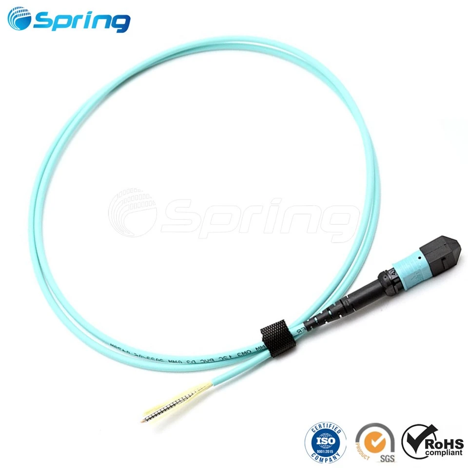
| Simplex Patch Cable | 1 fiber | 2.0 mm – 3.0 mm | Patch panels, equipment connections | 900 µm tight buffer, aramid yarn, PVC/LSZH jacket |
| Duplex Patch Cable | 2 fibers | 2.0 mm x 4.0 mm (Zipcord) | Enterprise LAN, Data Center SAN | Zipcord structure, dual tight buffer, color-coded |
| FTTH Flat Drop Cable | 1 – 4 fibers | 2.0 mm x 3.0 mm (Flat) | Last-mile subscriber access | Bow-type design, dual FRP or steel wire strength members |
| Indoor Distribution Cable | 4 – 144 fibers | 5.0 mm – 15.0 mm | Riser, Plenum, Building Backbone | Multi-unit tight buffers, flame-retardant outer jacket |
| Outdoor Loose Tube | 12 – 288 fibers | 8.5 mm – 18.0 mm | Duct & Direct Burial Backbones | Gel-filled loose tubes stranded around central FRP/steel |
| Armored Fiber Cable | 4 – 144+ fibers | 9.0 mm – 22.0 mm | Direct Burial, Harsh Industrial | Corrugated Steel Tape (CST) armor, double PE jackets |
| ADSS Aerial Cable | 12 – 288 fibers | 9.5 mm – 20.0 mm | Utility Pole Overhead Runs | All-dielectric, heavy aramid yarn layer, tracking-resistant jacket |
| Micro Loose Tube | 24 – 576 fibers | 5.5 mm – 12.5 mm | Air-blown microduct networks | High-density compact jacket, reduced wall thickness |
Fiber Color Coding & Tube Construction Limits
Understanding how optical fibers are packed inside buffer tubes clarifies why cable diameters step up at specific fiber count thresholds.
Telecommunications standards (TIA/EIA-598-D) utilize a 12-color identification sequence for optical fibers and buffer tubes:
Blue | 2. Orange | 3. Green | 4. Brown | 5. Slate | 6. White | 7. Red | 8. Black | 9. Yellow | 10. Violet | 11. Rose | 12. Aqua
How Tube Capacity Impacts Overall Cable Outer Diameter (OD)
In loose tube outdoor cables (e.g., GYTS, GYTA), fibers are grouped into gel-filled buffer tubes, typically housing 6 or 12 fibers per tube:
Up to 72 Fibers: A standard 6-loose-tube layer design (6 tubes x 12 fibers = 72 fibers) wrapped around a central strength member maintains a compact outer diameter of approximately 10.0 mm to 10.5 mm.
96 to 144 Fibers: Requires a double-layer loose tube construction or larger central strength member, increasing the overall cable diameter to 13.5 mm – 15.0 mm.
288 Fibers and Beyond: Employs multi-layer stranded designs or high-density micro-tubes to balance tensile performance and duct clearance.
Technical Specifications: Outdoor Loose Tube Armored Cable (GYTS / GYTA)
To assist network engineers in precise duct sizing and transport planning, the table below provides real-world dimensions, nominal weights, and mechanical tolerances for standard outdoor corrugated steel armored cables (GYTS type):
| Fiber Count | Loose Tube Count x Fibers/Tube | Cable Outer Diameter (OD) | Nominal Cable Weight (kg/km) | Max Pulling Force (Short Term) | Crush Resistance (Short Term) |
| 12 Fibers | 1 tube x 12 fibers (+Filler tubes) | 10.0 mm ± 0.5 mm | 105 kg/km | 1500 N | 1000 N / 100 mm |
| 24 Fibers | 2 tubes x 12 fibers (+Filler tubes) | 10.0 mm ± 0.5 mm | 108 kg/km | 1500 N | 1000 N / 100 mm |
| 48 Fibers | 4 tubes x 12 fibers (+Filler tubes) | 10.2 mm ± 0.5 mm | 112 kg/km | 1500 N | 1000 N / 100 mm |
| 72 Fibers | 6 tubes x 12 fibers | 10.5 mm ± 0.5 mm | 120 kg/km | 1500 N | 1000 N / 100 mm |
| 96 Fibers | 8 tubes x 12 fibers | 12.5 mm ± 0.5 mm | 150 kg/km | 1500 N | 1000 N / 100 mm |
| 144 Fibers | 12 tubes x 12 fibers (2 Layers) | 14.2 mm ± 0.5 mm | 195 kg/km | 1500 N | 1000 N / 100 mm |
| 288 Fibers | 24 tubes x 12 fibers (2 Layers) | 17.8 mm ± 0.5 mm | 280 kg/km | 3000 N | 1000 N / 100 mm |
Fiber Optic Cable Cross Section: What Does a Fiber Cable Look Like?
To visualize how microscopic glass fibers transform into a rugged physical cable, examine the internal cross section of an outdoor armored optical cable:

Key Structural Layers Explained:
Central Strength Member (CSM): Located at the geometric center of the cable, a solid FRP rod or stranded steel wire provides structural rigidity to prevent cable buckling under tension or extreme temperature fluctuations.
Buffer Tubes: High-modulus plastic PBT (Polybutylene Terephthalate) tubes containing colored 250 µm fibers floating freely inside water-resistant thixotropic gel.
Water-Blocking System: Synthetic dry water-swellable tape or yarns wrapped around the stranded cable core. Upon contact with moisture, these materials instantly swell to block water propagation.
Metallic Armoring Layer: Corrugated Steel Tape (CST) longitudinal armor bonded to the outer jacket. Provides extreme crush resistance (up to 1000 N / 100 mm) and prevents rodent attack in direct burial installations.
Outer Protection Sheath: A high-density polyethylene (HDPE/PE) jacket designed to withstand UV radiation, chemical exposure, and mechanical abrasion.
Engineering Rules: What Determines Fiber Cable Size & Selection?
Selecting the optimal fiber optic cable size requires balancing required bandwidth, mechanical protection, and physical installation constraints. Telecom field engineers evaluate three primary calculations:
1. Conduit Fill Capacity Rule (40% Rule)
When pulling fiber optic cables through underground conduits or innerducts, the maximum cross-sectional area occupied by the cable(s) must not exceed 40% of the conduit's internal cross-sectional area. This rule prevents excessive pulling friction and jam ratios.
Conduit Fill Calculation:
Cable Cross-Sectional Area = (Cable OD / 2)² x 3.1416
Conduit Cross-Sectional Area = (Conduit ID / 2)² x 3.1416
Fill Ratio = (Cable Area / Conduit Area) x 100% (Must be less than or equal to 40%)
Example: If deploying a 12.5 mm OD armored 96-core fiber cable, the minimum recommended conduit inside diameter (ID) is approximately 19.8 mm. (A standard 1-inch / 25 mm innerduct is recommended for smooth installation).
2. Minimum Bend Radius Calculation
Bending a fiber optic cable beyond its structural limit induces microbending loss, signal attenuation, and potential glass fracture. Cable outer diameter directly determines the required bending radius:
Dynamic Installation Bend Radius (20x Cable OD): The minimum radius allowed while pulling the cable under tension around corners or through sheaves.
Static Post-Installation Bend Radius (10x Cable OD): The minimum radius allowed after the cable is permanently secured in place.
Engineering Tip: For an outdoor armored cable with a 14.0 mm OD, the dynamic installation bend radius is 20 x 14.0 mm = 280 mm (11.0 inches).
3. Mechanical Strength vs. Outer Diameter
A larger outer diameter typically corresponds to additional protective layers and higher weight. For overhead utility installations, All-Dielectric Self-Supporting (ADSS) cables utilize thick outer jackets and extra aramid yarn layers to withstand high wind loads and ice accumulation without adding conductive metal elements.
Frequently Asked Questions About Fiber Cable Dimensions
What is the diameter of a standard fiber optic cable?
Indoor single-fiber patch cables measure 2.0 mm to 3.0 mm in diameter. Flat outdoor FTTH drop cables measure approximately 2.0 mm x 3.0 mm. Multi-loose-tube outdoor backbone cables range from 9.0 mm to 18.0 mm, depending on fiber count, armor type, and jacket layers.
What is the core size of single-mode fiber vs. multimode fiber?
Single-mode fiber features a 9 micron (µm) core size with a 125 µm cladding. Multimode fiber features either a 50 micron (µm) core (OM2/OM3/OM4/OM5) or a 62.5 micron (µm) core (OM1), both utilizing a 125 µm cladding diameter.
Does a higher fiber count always mean a thicker cable outer diameter?
Not necessarily. While traditional loose-tube cables increase in diameter as fiber counts rise, advanced ribbon fiber cables and micro-loose-tube designs can pack up to 288 or 576 fibers into compact outer diameters under 12.5 mm for air-blown microduct installations.
What is the difference between tight-buffered and loose-tube cable dimensions?
Tight-buffered indoor cables apply a 900 µm protective plastic layer directly onto the 250 µm fiber, making them ideal for flexible indoor distribution. Loose-tube cables place fibers inside gel-filled plastic tubes, allowing the fibers to move freely without stress under extreme thermal fluctuations, making loose-tube designs the standard for outdoor installations.
Conclusion: Custom Fiber Cable Manufacturing & Selection
Selecting the correct fiber optic cable dimensions involves balancing fiber count requirements, tensile load limits, crush resistance, and conduit capacity constraints. Matching the proper cable construction-from lightweight FTTH drop lines to armored loose tube outdoor backbones-ensures maximum transmission reliability and long-term network efficiency.
As an established OEM optical fiber cable manufacturer, Spring Optical specializes in custom cable engineering, tailored fiber counts, flame-retardant jacket options, and optimized outer diameters for telecom operators, ISPs, and distributors globally.
Contact Spring Optical today to request detailed product data sheets, custom cable outer diameter specifications, or direct factory project quotations.