

Author: Hayden
This technical guide gives an overview of the differences between APC, UPC and PC fiber connectors. As the telecom industry develops and continues to grow, the way we use fiber in our networks has also changed. These advancements have necessitated the development and acceptance of new connectors and techniques for connecting fiber to the last mile. This guide provides an overview of the three most common fiber connector types and their applications as well as some best practices for the use of these connectors in today's modern networks.
PC (Physical Contact) Connector

PC connectors have a slightly convex end face and represent the first generation of improved connector polish. PC connectors ensure that the fibers' cores are always in physical contact with each other. The typical return loss for a PC connector will be > -40 db.
UPC (Ultra Physical Contact) Connector

UPC connectors are an upgrade to the PC connector with tighter polishing tolerances resulting in a smoother end face than the PC connector with a flat (0 degree) end face. The typical return loss for a UPC connector will be > -50 db to -55 db.
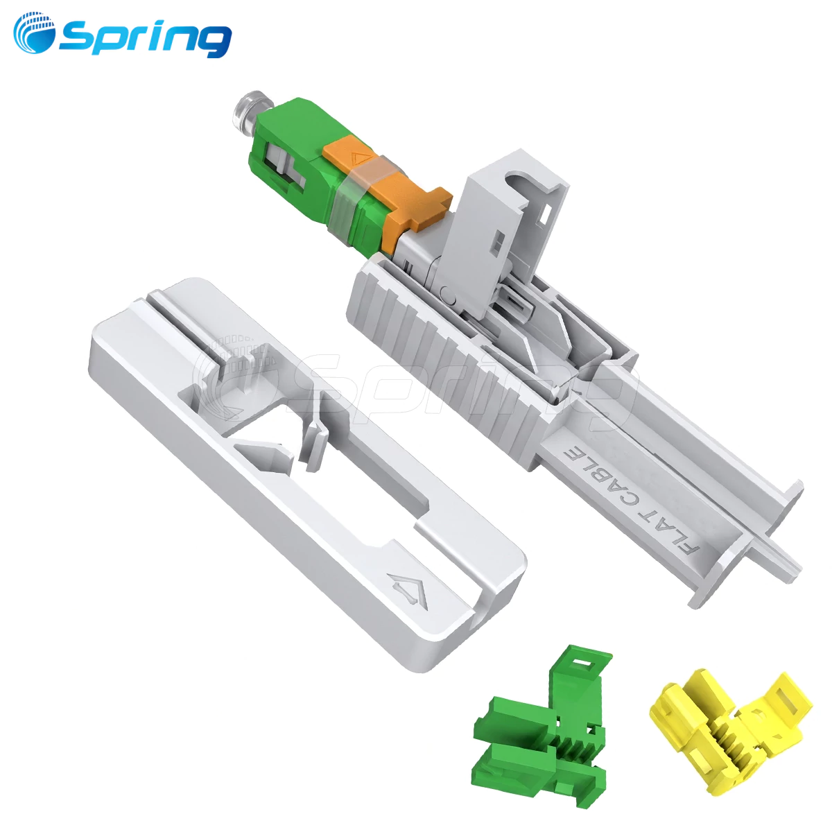
APC (Angled Physical Contact) Connector

APC connectors are identical to PC connectors except they have an angled end face that is polished at 8 degrees. The angle causes reflected light to be redirected back into the cladding of the fiber and thus reduces the amount of back reflection the connector creates. Typical return loss for APC connectors will be > -60 db and for premium connectors it can be > -65 db.
All three connectors utilize the same mechanical dimensions (2.5 mm ferrule for the SC, FC and ST connectors; and 1.25 mm for the LC connector). The only difference between the connectors is in the polishing style, but with the APC connector that the end face is polished at a - degree slant.
APC, UPC, and PC Fibre Connectors: A Brief Comparison Table
PC (Physical Contact), UPC (Ultra Physical Contact), and APC (Angled Physical Contact) Fibre Connectors
|
Parameter |
PC |
UPC |
APC |
|
End-face shape |
Convex, 0° |
Convex, 0° (ultra-smooth) |
Convex + 8° angle |
|
Typical Return Loss |
≥ -40 dB |
≥ -50 dB (-55 dB common) |
≥ -60 dB (-65 dB premium) |
|
Typical Insertion Loss |
0.2–0.5 dB |
≤ 0.3 dB (often ≤ 0.2 dB) |
≤ 0.3 dB |
|
Color code (SMF) |
Black / Beige |
Blue |
Green |
|
Color code (MMF) |
Beige / Black |
Beige |
Not used |
|
Reflection behavior |
Direct back to core |
Direct back to core |
Deflected into cladding |
|
Current usage |
Legacy, obsolete |
Enterprise LAN, data centers, NRZ links |
FTTx, CATV, WDM, PAM4, high-power systems |
|
System cost |
Low |
Medium |
High |
Tip: Color coding follows TIA/EIA and IEC standards: Blue = UPC, Green = APC (single-mode).
What is the Significance of Return Loss for APC vs. UPC vs. PC Fiber Connectors?
Return Loss (RL) is an assessment of the amount of light reflected back towards the source, which is represented as:
RL=−10×lg10(P0/P1)
(where P0 is the output power from the source and Pr is the received power). Therefore, a higher RL means that more of the light is not being returned, meaning better system performance.
The presence of reflected light on the return path has negative impacts that include:
An increase in the bit-error rate (BER) and in the number of pre-FEC errors, particularly in the use of PAM4 based data communication systems.
Possible fluctuation in laser output, which may lead to RIN (relative intensity noise).
Damage to high power transmitters (with power levels greater than 30 dBm when using Raman pump lasers).
The creation of ghost images and distortion in analog / RF video signals.
It is important to note that there is a varying degree of sensitivity to the physical connector type.
The following table summarizes the sensitivity to return reflection.
Now, let's review a case study on this topic of using UPC connectors in a deployment of 50G PAM4-based SPN and the associated impact on pre-FEC error rates and port flapping issues that occurred. The problem was solved once all of the UPC jumpers were replaced with APC jumpers.
Insertion Loss of Modern APC vs. UPC Fiber Connectors
Early generation APC connectors were prone to have an increased insertion loss as compared to UPC connectors because of the angle of the polished face. The advancements in precision polishing techniques and the development of high quality zirconia ferrules have allowed modern day APC connectors to achieve ≤0.3 dB IL just like UPC connectors do.
The main point to emphasise is that in present-day SM networks, using an APC does not restrict you to increased insertion losses.
Connector Housing Colour Codes

The colours of the housings of fibre optic connectors are indicative of the type of connector:
UPC: Blue housing for single mode fibre, Beige housing for multimode fibre
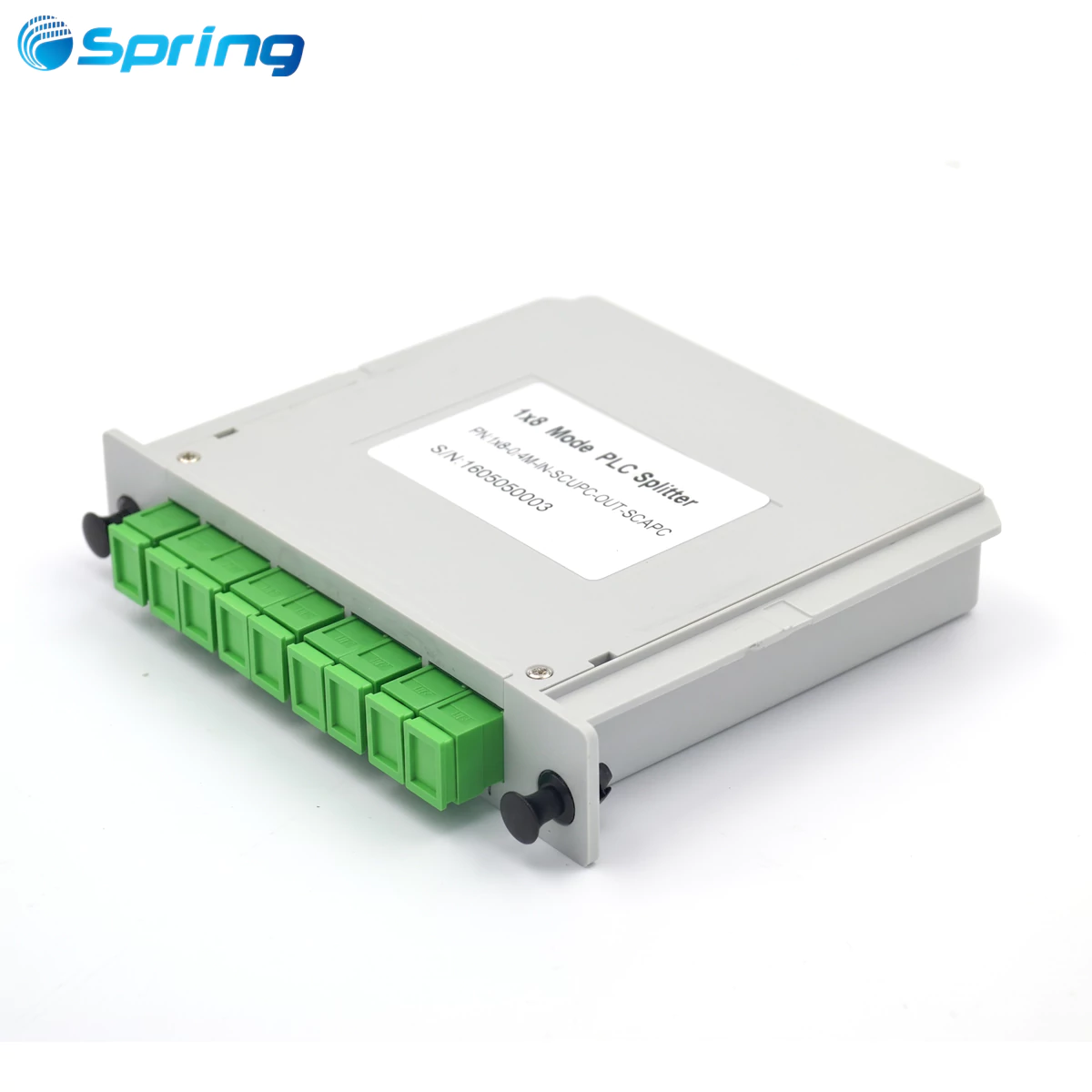
APC: Always Green
PC: Various colours, traditionally Black (single mode) and Beige (multimode)
Note: All types of fibre optic patch cords, adaptors and fibre attenuators are made with the same colour scheme as their connectors. Adding an illustration to demonstrate the end face angle of the connector and the applicable colour codes will help to improve the reader's understanding, as well as the effectiveness of alt tags for SEO.
Critical Compatibility Between APC, UPC, and PC Fiber Connectors
|
Connection |
Result |
Allowed? |
|
UPC ↔ UPC |
Normal IL & RL |
Yes |
|
APC ↔ APC |
Normal IL & RL |
Yes |
|
UPC ↔ PC |
Minor performance degradation |
Usually |
|
APC ↔ UPC/PC |
≥ 4–15 dB insertion loss, destroyed RL, possible ferrule damage |
NEVER |
Key Notes:
Never connect an APC connector directly into a standard UPC optical transceiver.
Always use a UPC-to-APC hybrid patch cord for connecting between polish types.
Mixing APCs with UPC/PCs creates an air gap between them, which could cause scratches on the ferrule.
Selecting APC, UPC, or PC Fiber Connectors for Your Network
Selecting APC for:
FTTx Deployments
CATV or RF video overlays
50G–800G PAM4 Coherent/Direct-detect Links
WDM/DWDM/CWDM Applications requiring >55 dB return loss
Using UPC when:
Data Centres & Networks with ≤25G distance between transceivers
Low Reflection sensitivity (budget-focused)
Test Equipment in Lab Environments
PC only chosen for:
Very Old OM1/OM2 Time-Sensitive Multimode Networks
Rare Use Cases
Industry Trends for APC vs. UPC vs. PC Fiber Connectors
APC connectors are increasingly favored for single-mode applications in PONs, coherent optics, and high-power systems.
UPC is still popular for short-reach applications, but APC adoption is growing rapidly within 400G-ZR/ZR+ and long-reach modules.
Q & A – Major Differences Between APC, UPC, PC Connectors
Q: Is an APC Always Better than a UPC Connector?
A: APC has better Return Loss Characteristics than UPC Connectors; however, gains are minimal for short-reach digital systems and enterprise applications.
Q: Is it Possible to Convert a PON Network from UPC to APC?
A: Yes! Modern Optical Network Terminals (ONTs) support APC connectors while maintaining compatibility with existing UPC infrastructure.
Q: Why Can't I Mate an APC Connector with a UPC Connector?
A: The 8° angle of the APC key creates an air gap, causing <4 dB insertion loss and almost zero return loss.
Q: Do All Transceivers Support APC?
A: No! Most standard QSFP modules and SFP/SFP+ connectors are UPC. Use hybrid APC-UPC jumpers when connecting APC lasers to UPC adapters outside the plant.
Q: Is Colour Coding Green and Blue Universal?
A: Yes. Colour coding is standardized by TIA/EIA and IEC. Blue = single-mode UPC, Green = single-mode APC.
Conclusions – Best Practices for Using APC, UPC, and PC Fiber Connectors
PC Connectors: Legacy multimode applications
UPC Connectors: Reliable for general digital systems
APC Connectors: Future-proof choice for new single-mode deployments
Connecting to PONs, CATV, or WDMs using APC connectors and green adapters ensures better return loss, higher system margin, and long-term stability.
NOTE: The connector polish type you select today will impact network performance for 10 to 20 years.