



1. Typical applications:
Fiber-to-the-home (FTTH) distribution
Long-haul trunk fiber lines
Campus and access networks
Underground or aerial fiber cable jointing
2. Scope of Application
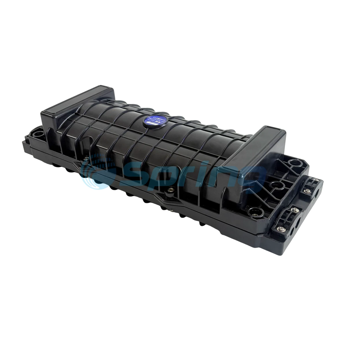
This installation manual applies to the GJS-H018 fiber optic splice closure. The closure supports multiple installation methods, including:
Aerial suspension
Direct-burial (underground)
Wall-mounted
Pipeline and duct mounting
Handhole and manhole integration
Operating temperature: –20°C to +65°C
Protection level: IP68
3. Technical Specifications
| Parameter | Specification |
|---|---|
| External Dimensions (L×W×H) | 413 × 160 × 88 mm |
| Net Weight | 1580g – 2100g |
| Cable Ports | 6 ports (3 per side) |
| Cable Diameter Supported | Ø8 – Ø16 mm |
| Max Fiber Capacity (Bunchy) | 96 cores |
| Max Fiber Capacity (Ribbon) | 144 cores |
4. Main Components
| No. | Component Name | Quantity | Description |
|---|---|---|---|
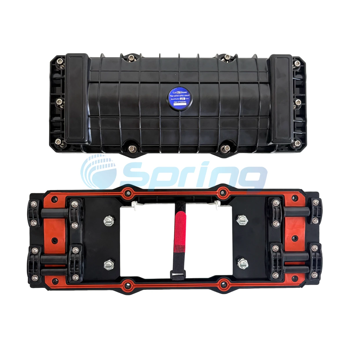
| 1 | Housing | 1 set | Protective shell for internal fiber splices |
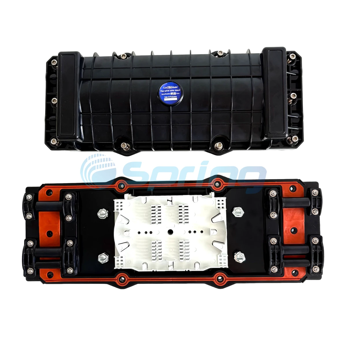
| 2 | Splice Tray (FOST) | Max. 2 pcs | Holds heat shrink sleeves and fiber routing |
| 3 | Foundation Plate | 1 set | Fixes trays and reinforced cores |
| 4 | Seal Fitting | 1 set | Ensures sealing between the cover and base |
| 5 | Port Plugs | 6 pcs | Seals unused ports |
| 6 | Earthing Device | 1 set | Grounds metallic fiber components (optional) |
5. Included Accessories
| Item | Function |
|---|---|
| Heat Shrink Sleeves | Protect fiber fusion points |
| Nylon Ties | Secure fibers within trays |
| Insulation Tape | Enlarge cable diameter for better fixation |
| Seal Tape | Improve port sealing compatibility |
| Abrasive Cloth | Prepares cable sheath for sealing |
| Labeling Paper | Identify fiber cores |
| Hanging Hook (Optional) | Aerial installation support |
| Earthing Wire (Optional) | Grounding support |
| M6 / M10 Wrenches | Tightening housing and reinforced nuts |
6. Required Tools (Provided by Installer)
Fiber cutter and stripper
Measuring tape
Screwdrivers (cross/parallel)
Scissors
Metal wrench
Ethyl alcohol and gauze for cleaning
Fusion splicing machine
7. Installation Process
Step 1: Open the Closure
Clean the work area and confirm the installation position.
Verify components and accessories in the package.
Loosen bolts and lift the cover-do not remove bolts completely to avoid misplacement.
Important: In poor weather conditions, use a protective tent for dust and waterproofing.
See Drawing 1

Step 2: Prepare Fiber Cables
Cut the cables to the following recommended lengths:
| Section | Length |
|---|---|
| From seal fitting to pressboard | 50 mm |
| For winding and splicing after stripping | 2020 mm |
| Fiber with a protective coat on the tray point | 420 mm |
| Bare fiber length for storage in FOST | 1600 mm |
See Drawing 2

Note: Stripping lengths may vary by installation requirement.
Step 3: Strip Protective Coats
Use a fiber stripper and cutter to strip the outer sheath based on the temporary locating marks.
If the sheath is hard to remove at once, strip in segments to avoid fiber damage.
See Drawing 3

Step 4: Separate Fibers & Prepare Cable
Use insulation tape on the fiber cable sheath.
Remove internal fillers, clean with alcohol.
Form coils (approx. Ø100mm) and secure with tape.
Reserve 40mm of reinforcing core and trim excess.
Important: Use seal tape to adjust smaller cable diameters to the port size.
See Drawing 4

Step 5: Fix Cable and Reinforced Core
Remove port plugs for the selected ports.
Insert the fiber cable and secure using the pressboard.
Tighten the reinforced core nut using the special M10 wrench.
Retighten with a metal wrench for better sealing pressure.
See Drawing 5

Ensure stripped cable sections align properly with fixing positions.
Step 6: Splice the Fibers
Follow the fusion splicer instructions to perform splicing.
Keep fiber twist and bend to a minimum. Use safety precautions for clean splices.
Step 7: Insert Heat Shrink Sleeves and House Fibers
Place the shrink sleeves with spliced fibers in the tray.
Form coils ≥80mm in diameter to maintain proper bend radius.
Fix fibers using nylon ties (avoid over-tightening).
See Drawing 6

Step 8: Final Check Before Sealing
Before reassembly:
Confirm fiber coil arrangement and bend radius.
Ensure all unused ports are plugged.
Verify all sealing tapes are neat and secure.
Tighten internal fasteners.
See Drawing 7

Step 9: Close and Lock Housing
Place the sealing gasket into position.
Place the cover onto the bottom housing.
Insert and tighten locating bolts with an M6 wrench.
For aerial installation, install the hanging hook before tightening the side bolts.
8. Testing & Inspection
Post-installation, perform the following standard tests:
| Test Item | Requirement |
|---|---|
| Sealing Performance | 100KPa ±5, no air bubbles after 15 min in water |
| Re-Sealing Performance | Same as above, after reopening and resealing |
| Tensile Strength | ≥800N axial pull |
| Compression Resistance | 2000N/10cm for 1 minute |
| Impact Resistance | 16N·m, 3 times, no cracks |
| Bending Test | ±45°, 150N, 10 cycles |
| Torsion Test | ±90°, 50N·m, 10 turns |
| Temperature Cycling | –40°C~+65°C, 10 cycles, ≤5KPa pressure loss |
| Voltage Withstand | 15KV DC, 1 min, no breakdown |
| Insulation Resistance | ≥2×10⁴ MΩ after immersion for 24h |
9. Packaging Contents
Each unit includes:
1 × GJS-H018 Fiber Splice Closure
Sealing accessories and trays
Installation manual
Port size measurement paper
Optional: pressure test valve or hanging hardware
Conclusion
The GJS-H018 is an advanced horizontal fiber optic splice closure offering exceptional protection, mechanical strength, and flexible installation across diverse scenarios. With IP68 sealing, high capacity, and ease of use, it ensures long-term fiber connectivity for telecom operators, ISPs, and FTTx projects.
Hot Tags: gjs-h018 horizontal fiber optic splice closure manufacturers, suppliers, factory, wholesale, customized, buy, bulk, in stock, free sample


