Author: CoCo coco@springoptic.com
Introduction: Why Optical Fiber PLC Splitters Matter in Modern FTTH Networks
An optical fiber PLC splitter is a core passive component in Fiber-to-the-Home (FTTH), FTTB, and PON access networks. It enables a single optical signal from the central office (CO) to be evenly distributed to multiple subscriber endpoints while maintaining signal stability, low insertion loss, and long-term reliability.
Among different packaging formats, the 0.9mm steel tube optical fiber PLC splitter-often referred to as a compact or micro-type PLC splitter-has become the preferred choice for space-constrained access networks, outdoor distribution points, and high-density Optical Distribution Network (ODN) architectures in North America and Europe.
What Is an Optical Fiber PLC Splitter?

A Planar Lightwave Circuit (PLC) splitter is an optical power management device fabricated using silica-based optical waveguide technology. Unlike traditional fused biconical taper (FBT) splitters, PLC splitters offer:
Wider operating wavelength range (1260–1650 nm)
Better channel uniformity
Higher reliability across temperature variations
Scalability from low to high split ratios
An optical fiber PLC splitter distributes optical signals from one or two input fibers to multiple output fibers (1×N or 2×N), making it an essential component in PON-based FTTH access networks.
Why Choose a Steel Tube (0.9mm) Optical Fiber PLC Splitter?
Compared with bare fiber PLC splitters, the steel tube optical fiber PLC splitter provides enhanced mechanical protection and environmental resistance.
Key Advantages of Steel Tube PLC Splitters
Stronger fiber protection than bare fiber designs
Stainless steel tube prevents fiber bending, crushing, and vibration damage
Compact form factor ideal for fiber distribution boxes, splice closures, and Multiport Service Terminals (MSTs)
Supports fusion splicing or connectorized termination
Excellent long-term stability in outdoor and harsh environments
Because of these characteristics, steel tube optical fiber PLC splitters are widely deployed in FTTH access networks, ODN nodes, and last-mile distribution points.
Steel Tube Size Options for Optical Fiber PLC Splitters
Steel tube PLC splitters are available in multiple standardized dimensions to suit different installation environments:
·60× 7 × 4 mm
·60 × 12 × 4 mm
·80 × 20 × 6 mm
·100 × 40 × 6 mm

The appropriate size depends on splitter ratio, fiber routing method, and enclosure space constraints-particularly when integrating splitters inside MST boxes or compact access terminals.
How Optical Fiber PLC Splitters Are Manufactured
The performance of an optical fiber PLC splitter is determined primarily during the manufacturing process. High-quality production follows three critical stages: Alignment, Bonding, and Sealing.
1. PLC Chip and Fiber Array Preparation
PLC Chips
High-precision bar-shaped PLC chips are sourced from established suppliers. Waveguide end faces are precision-polished to ensure optimal optical coupling.
Fiber Array Unit (FAU)

Multiple fibers (8, 16, 32, or more) are precisely aligned on a quartz V-groove substrate with matching waveguide spacing (typically 127 μm or 250 μm). Ultra-fine polishing minimizes coupling loss.
2. Active Alignment and Permanent Coupling
This is the most technically demanding step and directly determines insertion loss:

Six-axis precision alignment platform
Real-time optical power monitoring
Dynamic optimization of X/Y/Z axes and angular alignment
Permanent fixation using UV-curing adhesive or laser welding for premium-grade products
Only after achieving the optimal alignment point is the structure permanently bonded.

3. Packaging and Final Testing
Encapsulation in stainless steel or polymer housing

Silicone gel filling for shock absorption
Epoxy sealing for moisture and temperature resistance
Each optical fiber PLC splitter undergoes 100% performance testing, including:

Insertion loss per channel
Channel uniformity
Return loss
Polarization-dependent loss (PDL)
High/low temperature cycling tests (-40°C to +85°C)

Optical Fiber PLC Splitter Performance Parameters
|
|
1x2 |
1x4 |
1x8 |
1x16 |
1x32 |
1x64 |
|
|
Operating wavelength(nm) |
1260-1650 |
||||||
|
Insertion loss (dB) |
Typical |
3.6 |
7.2 |
10.5 |
13.5 |
17 |
19.5 |
|
Maximum |
4 |
7.5 |
11 |
14 |
17.2 |
21 |
|
|
Uniformity (dB) |
Typical |
0.4 |
0.5 |
0.6 |
1 |
1 |
2 |
|
Maximum |
0.6 |
0.6 |
0.8 |
1.2 |
1.5 |
2.5 |
|
|
Polarization Dependent Loss (dB) |
Typical |
0.1 |
0.1 |
0.15 |
0.2 |
0.2 |
0.2 |
|
Maximum |
0.15 |
0.15 |
0.25 |
0.3 |
0.3 |
0.3 |
|
|
Wavelength dependent loss (dB) |
Typical |
0.1 |
0.1 |
0.15 |
0.3 |
0.3 |
0.3 |
|
Maximum |
0.2 |
0.3 |
0.3 |
0.5 |
0.5 |
0.5 |
|
|
Return loss (dB) |
Minimum |
55/50 |
|||||
|
Directivity (dB) |
Minimum |
55 |
|||||
|
Operating temperature (℃) |
-20 to 85 |
||||||
|
Storage temperature (℃) |
-40 to 85 |
||||||
|
Optical fiber type |
SMF-28 Or customer required |
||||||
|
Optical fiber length (m) |
1.2 or customize |
||||||
Optical Fiber PLC Splitter Order Guide
| Item | Specification |
|---|---|
| Port | 1×N, 2×N |
| Fiber Type | G657A1, G657A2 |
| Package Type | 40×4×4, 50×7×4, 60×12×4, 60×7×4, 60×12×4, 80×20×6, 100×40×6, 100×80×10, 120×80×18 |
| Input Tube Diameter | 0.9 mm loose tube, 0.9 mm tight tube, 2.0 mm cable, 3.0 mm cable, 250 µm fiber, ribbon fiber |
| Output Tube Diameter | 0.9 mm loose tube, 0.9 mm tight tube, 2.0 mm cable, 3.0 mm cable, 250 µm fiber, ribbon fiber |
| Each Leg Length | 0.5 m, 1.0 m, 1.5 m |
| Input Connectors | SC/APC, SC/UPC, LC/APC, LC/UPC, FC/APC, FC/UPC, ST/UPC, No connectors |
| Output Connectors | SC/APC, SC/UPC, LC/APC, LC/UPC, FC/APC, FC/UPC, ST/UPC, No connectors |
How PLC Splitters, MST Box, and Drop Cables Work Together in FTTH Networks
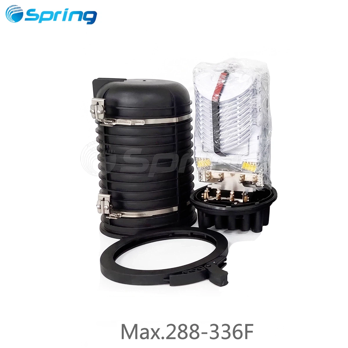
In a typical FTTH access network, the PLC splitter acts as the optical signal distribution point, dividing feeder fiber signals into multiple branches. These branches are routed and protected inside Multiport Service Terminal (MST), which provide structured fiber management and multiple subscriber-facing output ports.
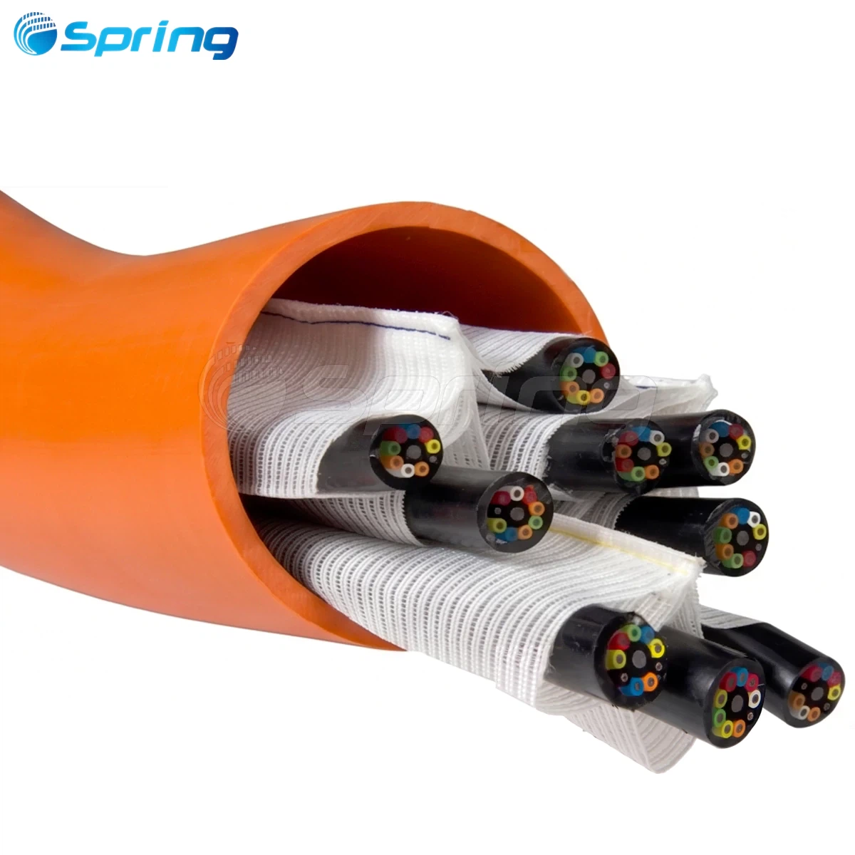
From the MST, optical signals are delivered to individual homes or buildings using FTTH drop cables, completing the last-mile fiber connection.
This layered architecture-PLC splitter → MST → drop cable-is widely adopted by ISPs to improve deployment efficiency, simplify maintenance, and support scalable network expansion.
Frequently Asked Questions About Optical Fiber PLC Splitters
What is a PLC splitter in fiber optic networks?
A PLC splitter is a passive optical component used in FTTH and PON networks to divide a single optical input into multiple output fibers. It enables point-to-multipoint transmission and forms a critical part of the optical distribution network.
What is a micro PLC splitter?
A micro PLC splitter refers to a compact-form PLC splitter designed for space-limited FTTH deployments. These splitters are commonly installed inside MST boxes or fiber distribution terminals, rather than housed in standalone splitter enclosures.
What is the difference between a micro PLC splitter and a box-type PLC splitter?
The difference is primarily packaging. Micro PLC splitters are intended for integration inside existing enclosures such as MST boxes or splice closures, while box-type PLC splitters are standalone units typically installed in central offices or street cabinets. Optical performance is comparable when manufacturing quality is equivalent.
Where are micro PLC splitters commonly used?
Micro PLC splitters are widely used in FTTH access networks, especially inside MST boxes, fiber splice closures, and compact distribution terminals where space efficiency and modular expansion are required.
Are micro PLC splitters suitable for outdoor FTTH deployments?
Yes. When installed inside sealed outdoor enclosures, micro PLC splitters provide reliable performance across wide temperature ranges and harsh environmental conditions typical of outdoor FTTH networks.
What splitter ratios are available for micro PLC splitters?
Common splitter ratios include 1×2, 1×4, 1×8, and 1×16. The appropriate ratio depends on subscriber density, optical power budget, and overall network design.
How do PLC splitters connect to FTTH drop cables?
In FTTH networks, output fibers from PLC splitters are routed through MST boxes and then connected to FTTH drop cables via fusion splicing or pre-terminated connectors, depending on deployment strategy and installation efficiency requirements.
Manufacturer Perspective: Engineering-Based Reliability
Spring is a fiber optic connectivity manufacturer focused on passive components for FTTH and access networks, including PLC splitters, MST boxes, fiber optic cables, and pre-terminated assemblies.
PLC splitters are produced under controlled manufacturing processes with full performance verification, including insertion loss consistency, uniformity, and environmental reliability. Product design emphasizes compatibility with modern FTTH architectures and real-world deployment conditions rather than laboratory-only specifications.

Conclusion
The 0.9mm steel tube optical fiber PLC splitter combines compact design, mechanical robustness, and stable optical performance, making it a practical solution for modern FTTH and access networks. By understanding its structure, manufacturing process, and role within the PLC → MST → drop cable architecture, network planners and procurement professionals can make informed decisions that support long-term network reliability and scalability.