



Author: Spring Optical Team
Spring Optical Team is a fiber optic industry expert group specializing in FTTx, FTTH, and FTTA solutions. We share insights on fiber technologies, product applications, and network deployments based on manufacturing and global project experience.
Last Updated: September 2, 2026
As Fiber-to-the-Home (FTTH) networks continue to expand across North America, broadband operators need network components that can simplify field installation, reduce labor requirements, and support faster subscriber connections.
An MST Fiber Terminal (Multiport Service Terminal) is one of the key components used to achieve this. Installed between the feeder fiber network and subscriber connections, an MST provides multiple hardened fiber ports in a sealed outdoor enclosure. Depending on the network design, it can provide direct fiber connections or integrate a PLC splitter for PON-based subscriber distribution.
This guide explains what an MST Fiber Terminal is, how it works, the main MST configurations, factory-attached stub cable options, port configurations, optical considerations, and how multiple MST terminals can be deployed in a Daisy Chain architecture.
What Is an MST Fiber Terminal?
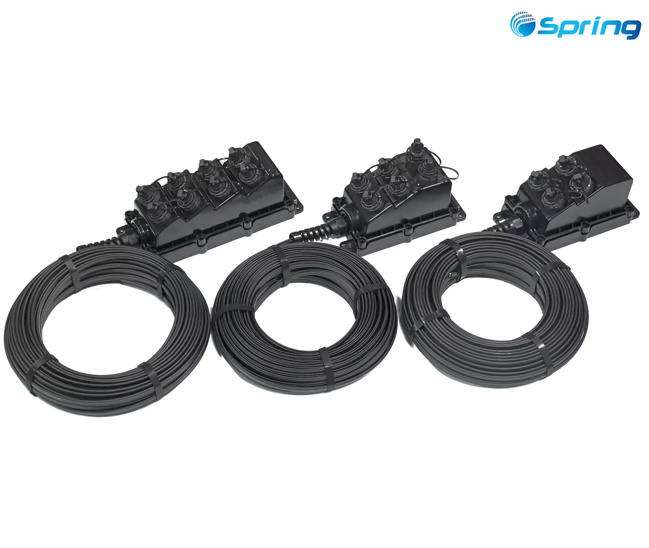
An MST Fiber Terminal is a sealed, multiport outdoor fiber access terminal used to connect feeder fibers with subscriber drop cables in FTTH and FTTx networks.
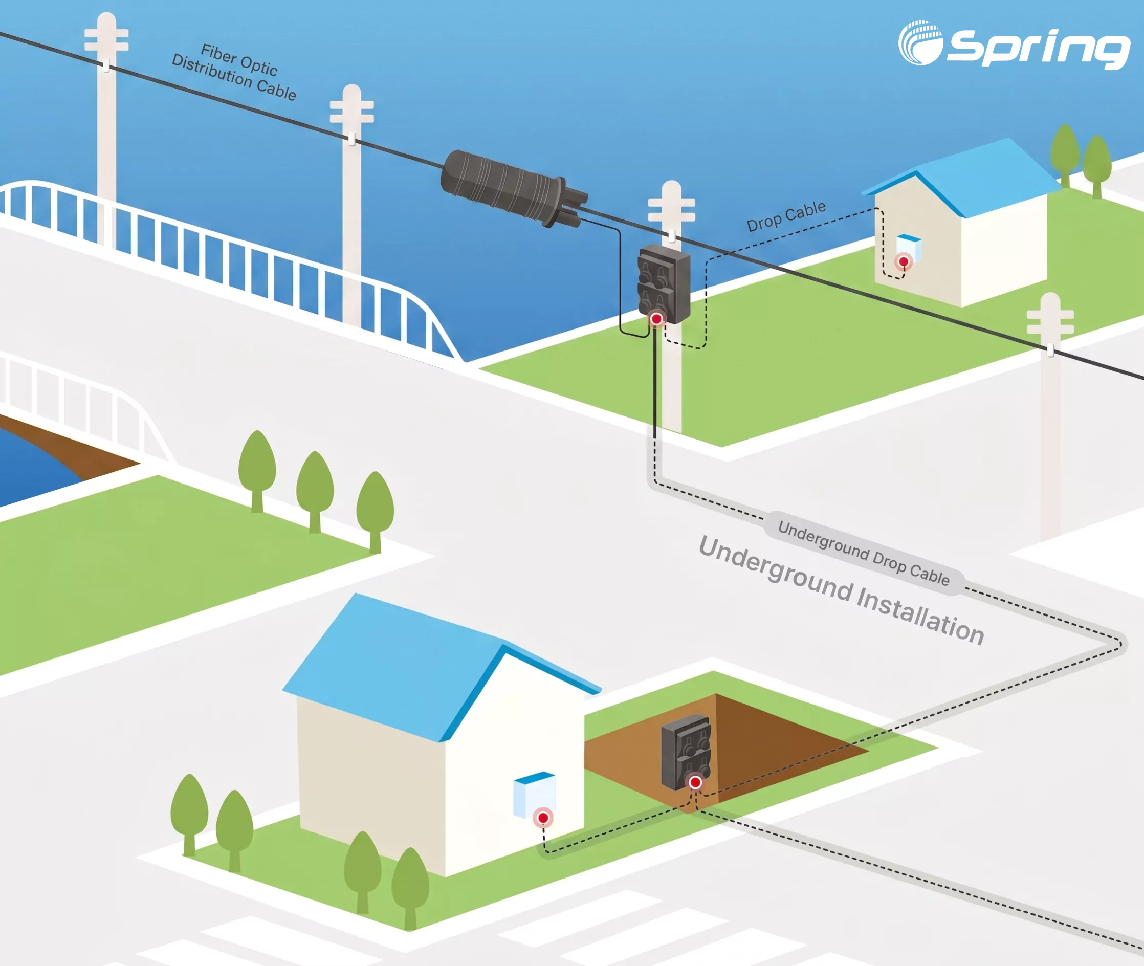
MST terminals are commonly installed on utility poles, aerial messenger strands, underground pedestals, handholes, and other outdoor telecom infrastructure.
A typical FTTH connection can be represented as:
OLT → Feeder Fiber → MST Fiber Terminal → Drop Cable → ONT
The feeder fiber brings the optical signal from the upstream network to the MST. The MST then provides multiple access ports where compatible subscriber cables can be connected.
This pre-terminated architecture can reduce routine field splicing and make subscriber activation more straightforward, particularly in large-scale FTTH deployments.
How Does an MST Fiber Terminal Work?
An MST Fiber Terminal provides a connection point between the feeder fiber network and subscriber drop cables.
A typical direct-fiber connection is:
OLT → Feeder Fiber → MST → Drop Cable → ONT
The MST receives feeder fibers and provides multiple hardened ports for connecting subscriber cables.
Depending on the network design, the MST can either provide direct fiber connections or integrate a PLC splitter to distribute one incoming optical signal to multiple subscriber ports.
For example, an MST with a 1×8 PLC splitter can be used in a PON network as:
Feeder Fiber → 1×8 PLC Splitter → 8 Subscriber Ports → Multiple Homes
The important distinction is that the MST is the outdoor fiber access terminal, while the PLC splitter is the optical component that divides one optical input into multiple outputs. A PLC splitter may be integrated inside an MST, but it is not what defines an MST.
Main Types of MST Fiber Terminals
MST Fiber Terminals can be configured according to the feeder connection method and optical distribution architecture.
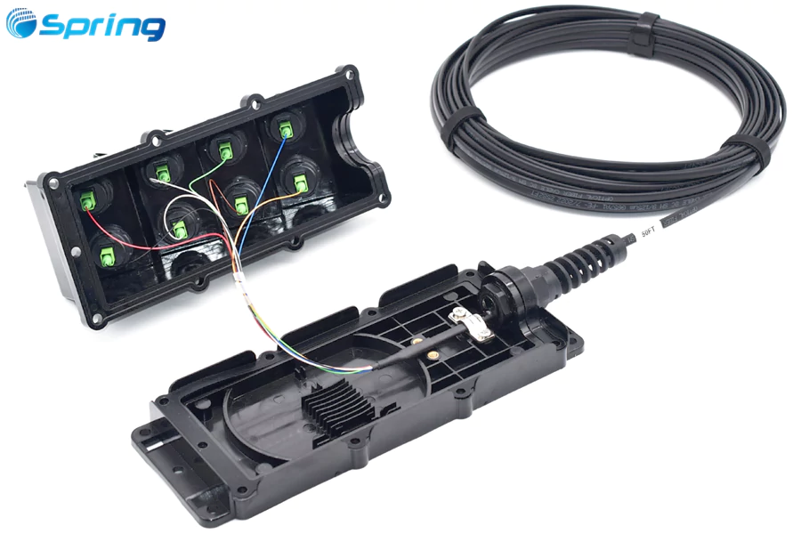
1. Stubbed MST Fiber Terminal Without PLC Splitter
A Stubbed MST Fiber Terminal includes a factory-attached feeder stub or tail cable.
In a non-splitter configuration, the incoming fibers are routed directly to the terminal ports without an internal PLC splitter.
This configuration is suitable for Point-to-Point fiber networks, enterprise connections, FTTA applications, and other dedicated fiber links.
Because the feeder stub is assembled and terminated at the factory, the MST can arrive at the job site as a preconfigured assembly, reducing field fiber preparation and splicing.
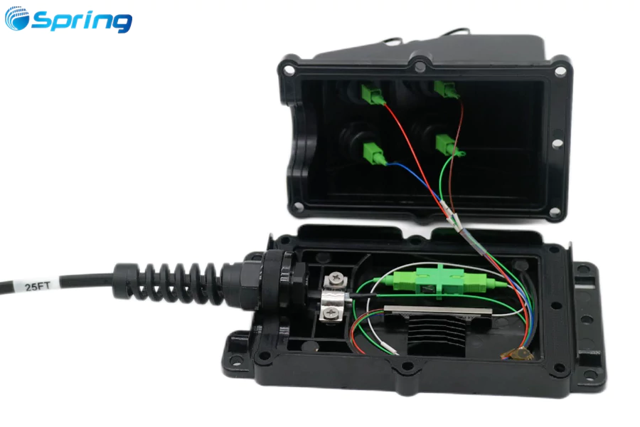
2. Stubbed MST Fiber Terminal With PLC Splitter
A stubbed MST can also integrate a PLC splitter inside the sealed terminal.
A typical configuration is:
1 Feeder Fiber → 1×N PLC Splitter → N Subscriber Ports
For example, a 1×8 splitter can distribute one incoming PON fiber to eight subscriber ports.
This configuration combines the factory-attached feeder stub, optical splitting, and subscriber access ports in a single outdoor assembly.
It is particularly useful for FTTH networks where multiple subscribers are distributed around the same service area.
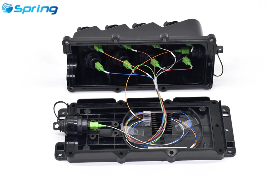
3. Stubless MST Fiber Terminal With PLC Splitter
A Stubless MST Fiber Terminal does not have a permanently attached feeder cable. Instead, it uses an external hardened connector interface for the feeder connection.
A typical architecture is:
Feeder Cable → Hardened Input Port → PLC Splitter → Hardened Output Ports
The modular structure can simplify network expansion, maintenance, and future reconfiguration.
Stubless MST terminals are useful when feeder cable routes, network configurations, or deployment phases may change over time.
Stubbed vs. Stubless MST Fiber Terminal
The primary difference is the way the feeder cable connects to the terminal.
| Feature | Stubbed MST | Stubless MST |
|---|---|---|
| Feeder connection | Factory-attached stub cable | External connector |
| Factory configuration | Highly preconfigured | Modular |
| Field flexibility | Lower | Higher |
| Typical use | Standardized FTTH deployment | Expansion and reconfiguration |
| Main advantage | Factory-integrated installation | Flexible field connection |
For projects with known feeder routes and cable lengths, a Stubbed MST can provide a highly standardized installation.
For networks that require frequent changes or future expansion, a Stubless MST can provide greater flexibility.
MST Fiber Terminal Stub Cable Options
For a Stubbed MST Fiber Terminal, the factory-attached feeder stub can be customized according to the installation environment, cable routing requirements, and fiber count.
Common stub cable constructions include SST Dielectric, SST Toneable, ROC Dielectric, ROC Toneable, Fig-8 Flat, and Circular Cable.
| MST Stub Cable Type | Typical Size | Installation | Fiber Count | Connector Options |
|---|---|---|---|---|
| SST Dielectric | 4.5 × 8.0 mm | Aerial / Buried | 1–12 | Opti-compatible / SC/APC |
| SST Toneable | 4.5 × 9.8 mm | Aerial / Buried | 1–12 | Opti-compatible / SC/APC |
| ROC Dielectric | 3.0 × 5.4 mm | Aerial / Buried | 1–12 | Opti-compatible / SC/APC |
| ROC Toneable | 3.0 × 6.6 mm | Aerial / Buried | 1–12 | Opti-compatible / SC/APC |
| Fig-8 Flat | 2.0 × 5.0 mm | Aerial | 1–4 | Opti-compatible / SC/APC |
| Circular | 5.0 mm | Aerial | 1–2 | Opti-compatible / SC/APC |
Dielectric constructions are suitable when an all-dielectric cable is required, while toneable constructions can be used when underground cable locating is required. Fig-8 and circular cables can be selected for specific aerial installation requirements.
The factory-attached stub can be supplied in the required length and factory-terminated with the specified connector configuration.
Note: Cable dimensions, fiber counts, connector types, and available configurations should be confirmed against the specific MST model and project requirements.
How Many Ports Does an MST Fiber Terminal Have?
MST Fiber Terminals are commonly available in 2, 4, 6, 8, 10, 12, and 16-port configurations.
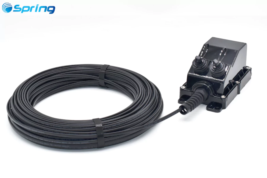
2 Port MST Fiber Terminal
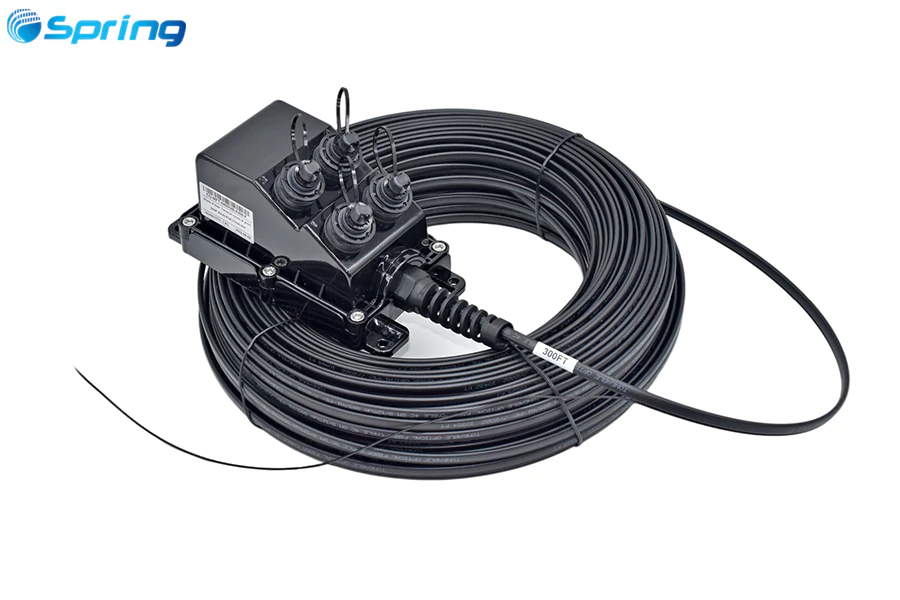
4 Port MST Fiber Terminal
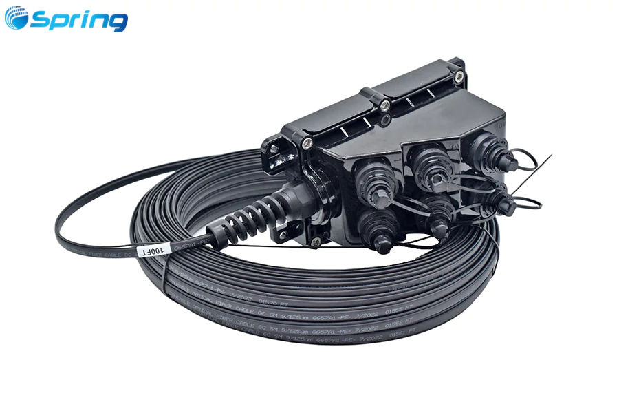
6 Port MST Fiber Terminal
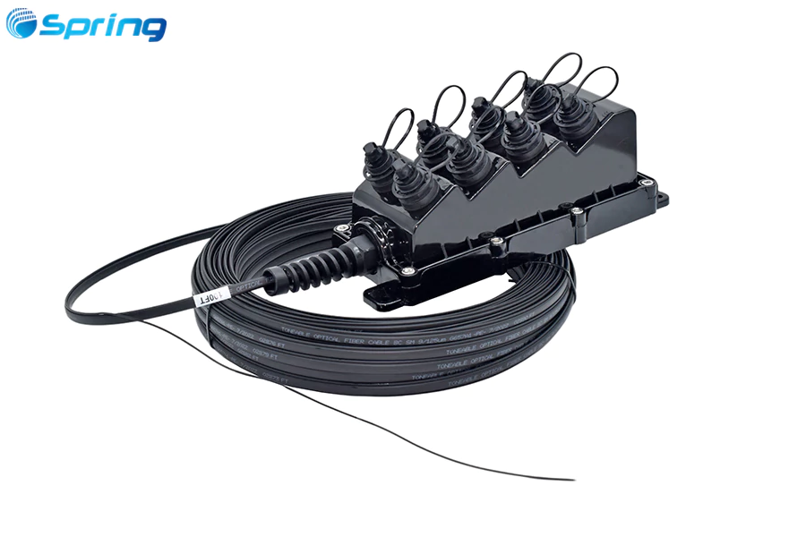
8 Port MST Fiber Terminal
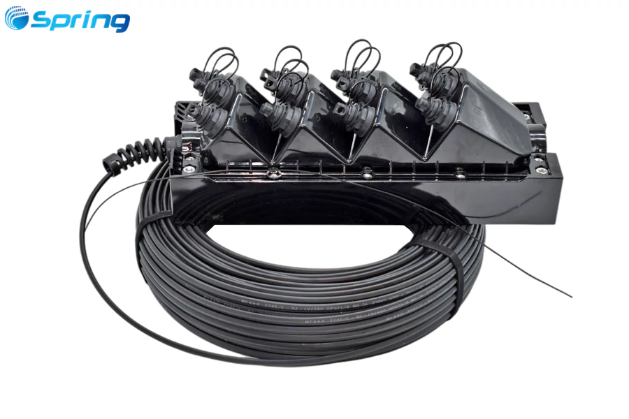
12 Port MST Fiber Terminal
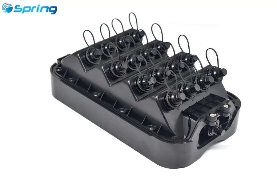
16 Port MST Fiber Terminal
The appropriate port count depends on subscriber density, network architecture, installation location, and future expansion requirements.
| Network Environment | Typical MST Configuration |
|---|---|
| Low-density rural broadband | 2–4 ports |
| Standard residential FTTH | 6–8 ports |
| High-density residential areas | 10–16 ports |
| Dedicated fiber services | Direct-fiber configuration |
| PON subscriber distribution | MST with PLC splitter |
For PON networks, the number of subscribers supported is also determined by the splitter ratio and available optical power budget.
A 1×4, 1×8, or 1×16 PLC splitter provides 4, 8, or 16 optical output paths respectively. However, the final network design must also account for splitter loss, fiber attenuation, connector insertion loss, and splice loss.
How to Choose the Right MST Fiber Terminal
Selecting an MST should start with the network architecture, not simply the number of ports.
Port count should match the current subscriber density while providing appropriate capacity for future expansion.
PLC splitter configuration should be selected according to whether the network requires direct fiber connections or PON-based optical distribution.
Stubbed or stubless design should be determined by the feeder connection method and the expected need for future network changes.
Stub cable construction should match the installation environment. Aerial, buried, toneable, and all-dielectric requirements can lead to different cable selections.
Connector compatibility is also critical when the MST is connected to hardened drop cables or other pre-terminated fiber assemblies.
Finally, the complete optical link should be evaluated using an optical power budget that includes fiber attenuation, splitter loss, connector loss, and splice loss.
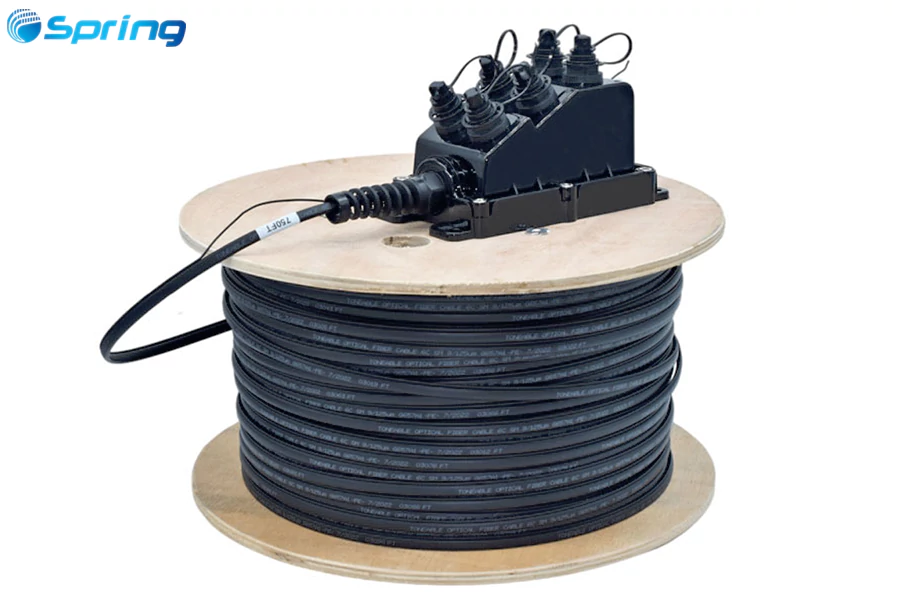
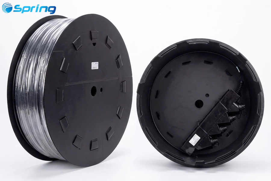
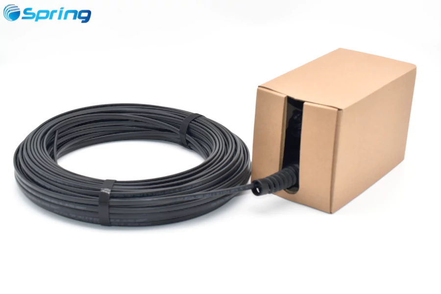
Packaging options should also be considered based on the MST configuration, stub cable length, and transportation requirements. Available packaging solutions may include cardboard reels, cylindrical cardboard boxes, mini boxes, and wooden reels to provide appropriate protection during storage and shipment.
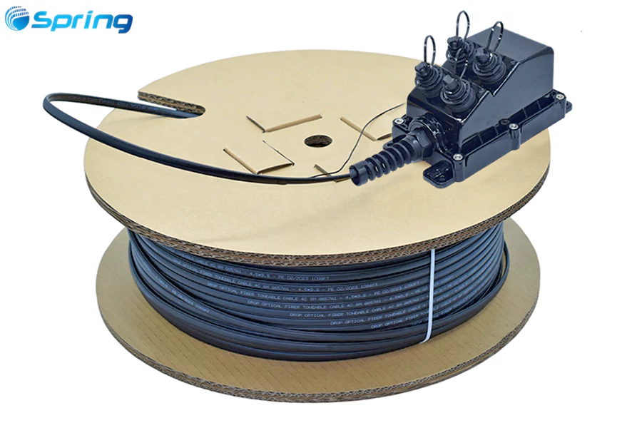
Step-Down Daisy Chain MST Architecture
In a conventional FTTH network, feeder fibers may be routed from an upstream distribution point toward different service areas.
When subscribers are distributed along a long road or utility route, however, not every feeder fiber needs to be accessed at every location.
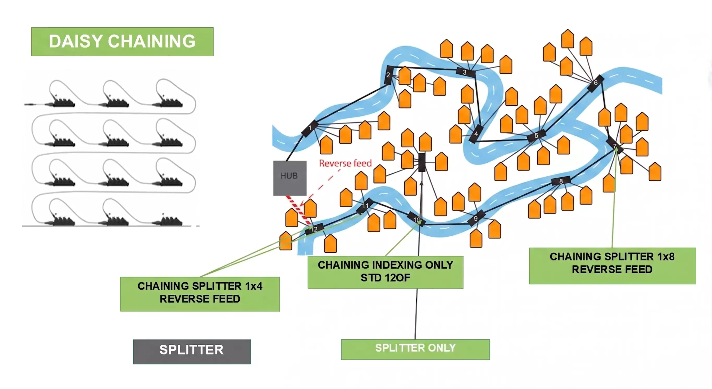
A Daisy Chain architecture provides another option: multiple MST Fiber Terminals are installed sequentially along the same feeder route.
The concept is:
Feeder Cable → MST 1 → MST 2 → MST 3 → MST 4
At MST 1, the fibers required for the local service area are accessed. The remaining fibers continue downstream to MST 2.
MST 2 can then access the fibers needed for its local subscribers, while other unused fibers continue toward MST 3.
This allows one multi-fiber feeder cable to support multiple MST locations along the route.
Example: One 24-Fiber Feeder Cable Serving Multiple MSTs
Consider a network using a 24-fiber feeder cable with seven MST terminals distributed along a residential route.
At the first MST, several fibers can be accessed to serve nearby subscribers. For example, one fiber could feed an internal 1×4 PLC splitter, while other fibers could be reserved for dedicated connections.
The remaining fibers continue toward the next MST.
At each downstream MST, additional fibers can be accessed according to local subscriber requirements while unused fibers continue further downstream.
The key principle is:
Use the fibers required at each MST → Pass the remaining fibers downstream → Repeat at the next MST.
This approach can improve feeder fiber utilization in linear FTTH deployments and may reduce the amount of dedicated feeder cabling required.
However, Daisy Chain design must always be evaluated against the available optical power budget and the physical limitations of the feeder cable.
Optical Power Budget for MST Networks
An MST deployment should not be designed solely around fiber count or port count.
The complete optical path must remain within the available power budget.
A simplified link-loss calculation is:
Total Link Loss = Fiber Attenuation + Splitter Loss + Connector Loss + Splice Loss
For a PON network, the calculation may include the loss of the PLC splitter, upstream and downstream connector interfaces, fiber length, and any intermediate splices.
For Daisy Chain architectures, additional connector and splice points can accumulate along the route, making optical budget analysis particularly important.
The final design should be checked against the optical budget requirements of the selected OLT, ONT, and PON technology.
MST Fiber Terminal Technical Specifications
MST specifications vary according to the terminal design, connector system, feeder configuration, and project requirements.
| Parameter | Typical Specification |
|---|---|
| Product | Outdoor Multiport Service Terminal |
| Fiber Type | Single-Mode |
| Common Fiber | G.657.A1 / G.657.A2 |
| Port Count | 2 / 4 / 6 / 8 / 10 / 12 / 16 |
| Terminal Configuration | Stubbed / Stubless |
| PLC Splitter | Optional |
| Connector | Hardened Connector / Mini SC / Other Compatible Interfaces |
| Stub Cable | Dielectric / Toneable / Fig-8 / Circular |
| Installation | Aerial / Underground / Pole / Pedestal / Handhole |
| Stub Cable Length | Standard or Customized |
Actual specifications should always be confirmed against the selected MST model and project requirements.
MST Fiber Terminal Testing and Reliability
Because MST Fiber Terminals are designed for long-term outdoor deployment, mechanical reliability, environmental protection, and optical performance are important.
Depending on the product design and customer requirements, testing may include insertion loss, return loss, optical continuity, connector durability, cable retention, tensile performance, vibration, temperature cycling, water ingress resistance, and UV exposure.
For products designed or qualified to specific telecom standards, the applicable requirements and test documentation should be verified for the specific product.
Reliability should also be evaluated at the system level. The MST enclosure, connector interface, factory-attached stub, and cable assembly must all be suitable for the intended outdoor environment.
Hardened Connector Options for MST Fiber Terminals
The connector interface is a critical part of an outdoor MST system.
Depending on the application, MST Fiber Terminals may be configured with OptiTap-compatible hardened connectors, Mini SC, ODVA, ODC, PTLC, PTMPO, or other hardened interfaces.
Before deployment, the mechanical and optical compatibility between the MST and the mating cable assembly should be verified.
Important parameters include connector type, fiber type, end-face configuration, cable dimensions, sealing requirements, and environmental specifications.
Connector compatibility should always be confirmed from the actual product specifications rather than connector appearance or naming alone.
MST Fiber Terminal Applications
Rural Broadband
MST Fiber Terminals are well suited to rural broadband networks where subscribers may be distributed along long aerial or underground routes.
A strategically positioned MST can provide a local access point for multiple homes without requiring a separate distribution enclosure at every subscriber location.
Suburban FTTH
In suburban residential networks, MST terminals can be installed along aerial or underground fiber routes.
When a subscriber is activated, technicians can connect a compatible pre-terminated drop cable directly to an available MST port, simplifying the field installation process.
MDU and Community Networks
For apartment complexes, gated communities, and multi-building developments, higher-port-count MST terminals can provide a centralized outdoor access point for multiple subscriber connections.
FTTA and Small Cell Networks
Hardened outdoor fiber terminals can also be used in Fiber-to-the-Antenna (FTTA) and small-cell deployments where fiber connectivity must withstand outdoor environmental conditions.
MST Fiber Terminal FAQ
What is an MST Fiber Terminal?
An MST Fiber Terminal is a sealed, multiport outdoor fiber access terminal used to connect feeder fibers with subscriber cables. It provides a standardized connection point for FTTH and FTTx networks.
What does MST stand for in fiber optics?
MST stands for Multiport Service Terminal. It is a multiport fiber access terminal designed to provide connections between the feeder network and subscriber or distribution cables.
Is an MST Fiber Terminal compatible with Opti drop cables?
An MST can be configured with Opti-compatible hardened interfaces, but actual compatibility should always be confirmed against the connector specifications of both the MST and mating cable assembly.
What is the difference between a stubbed and stubless MST?
A stubbed MST has a factory-attached feeder stub cable, while a stubless MST uses an external connector interface. Stubbed designs are generally suited to standardized deployments, while stubless designs provide greater modularity for network expansion and reconfiguration.
What types of stub cables are available for an MST?
Common factory-attached stub options include SST Dielectric, SST Toneable, ROC Dielectric, ROC Toneable, Fig-8 Flat, and Circular Cable. The appropriate construction depends on the installation environment, fiber count, cable routing, and connector requirements.
How many ports can an MST Fiber Terminal have?
Common configurations include 2, 4, 6, 8, 10, 12, and 16 ports. The correct port count depends on subscriber density, network architecture, and future expansion requirements.
Can multiple MST terminals share one feeder cable?
Yes. Multiple MST terminals can be installed along the same feeder route using a Daisy Chain architecture. Each MST can access the fibers required for its local service area while unused fibers continue downstream. The complete optical link must remain within the available optical power budget.
Can an MST be supplied with a factory-terminated stub cable?
Yes. Stubbed MST Fiber Terminals can be supplied with factory-attached feeder cables in different constructions, lengths, fiber counts, and connector configurations according to project requirements.
Does an MST eliminate all field splicing?
Not necessarily. A pre-terminated MST system can significantly reduce routine subscriber-side field splicing, but splicing may still be required elsewhere in the feeder or distribution network depending on the overall ODN architecture.
Related MST and FTTH Deployment Guides
What Is a Pre-Connectorized Drop Cable? The Definitive Outdoor FTTH Guide
What Is the Purpose of the MST Multiport Service Terminal?
Multiport Service Terminal (MST) for FTTH: Complete Guide to Architecture, Deployment, Cost & ROI
Custom MST Box for Fiber Deployment
Final Thoughts
An MST Fiber Terminal is more than a multiport fiber connection box. It is an important component of a pre-connectorized FTTH architecture, providing a standardized connection point between the feeder network and subscriber access network.
The right MST configuration depends on more than port count. Network designers should evaluate the stubbed or stubless architecture, PLC splitter configuration, connector interface, factory-attached stub cable construction, subscriber density, installation environment, optical power budget, and future expansion requirements.
For distributed FTTH networks, a Step-Down Daisy Chain topology can provide another design option by allowing multiple MST terminals to share a common feeder route while accessing only the fibers required at each location.
Ultimately, the best MST solution is not necessarily the terminal with the most ports. It is the solution correctly matched to the network architecture, deployment environment, optical budget, installation method, and long-term operational requirements.
About Spring Optical
Spring Optical provides fiber connectivity solutions for FTTH, FTTx, broadband, and outdoor fiber networks, including Multiport Service Terminals, factory-terminated MST assemblies, hardened fiber connectivity systems, PLC splitter solutions, outdoor fiber cables, and OEM/ODM products.
For an MST Fiber Terminal project, key specifications to define include port count, connector interface, stubbed or stubless design, fiber type, PLC splitter ratio, stub cable construction, cable length, pre-termination requirements, installation method, and environmental requirements.
By combining the MST Fiber Terminal with compatible pre-terminated cable assemblies and an appropriate network topology, network operators can build a more standardized, scalable, and field-efficient FTTH access network.