Author: Lisa lisa@springoptic.com
Introduction – What are PON Splitters in Fiber Optic Networks
In the modern Passive Optical Network (PON) architecture, the optical splitters act as the important elements in the distribution process of the optical signals of oxygen from one fibre feeder to several other endpoints. For the design engineers involved in planning a Fibre to the X (FTTX) networks, the selection of the balanced optical splitters or unbalanced optical splitters) are significant to the final performance and the ultimate cost. This full informative guide will look at both splitter types in relation to the pre-terminated ODN system allowing for granting expert information in gaining the full advantage for the design of the optimum network implementation.
What is Balanced Optical Splitters - Equal Power Distribution

A balanced optical splitter is one where the optical power which is fed into the splitter is dispersed equally among the functional output ports, this making them suitably equipped for any operation where equal signal levels would have to be maintained between all the terminals.
Technical for example - In a 1 x 4 balanced splitter all the outputs would be drawing approximately 25% of the result in the overall incoming optical power. This allows for equal performance with all the customers connected to a balanced system for telemarketers.
Some key points related to Balanced Splitters:
Insertion Loss – Theoretical loss is approximately 6 dB per output port will be experienced with practical devices usually showing ~7 dB reduced signal due to excess loss and connector loss
Network Topology – Takes the form of a star in which each independent output requires a dedicated fibre run back to the Central Office or distribution cabinet
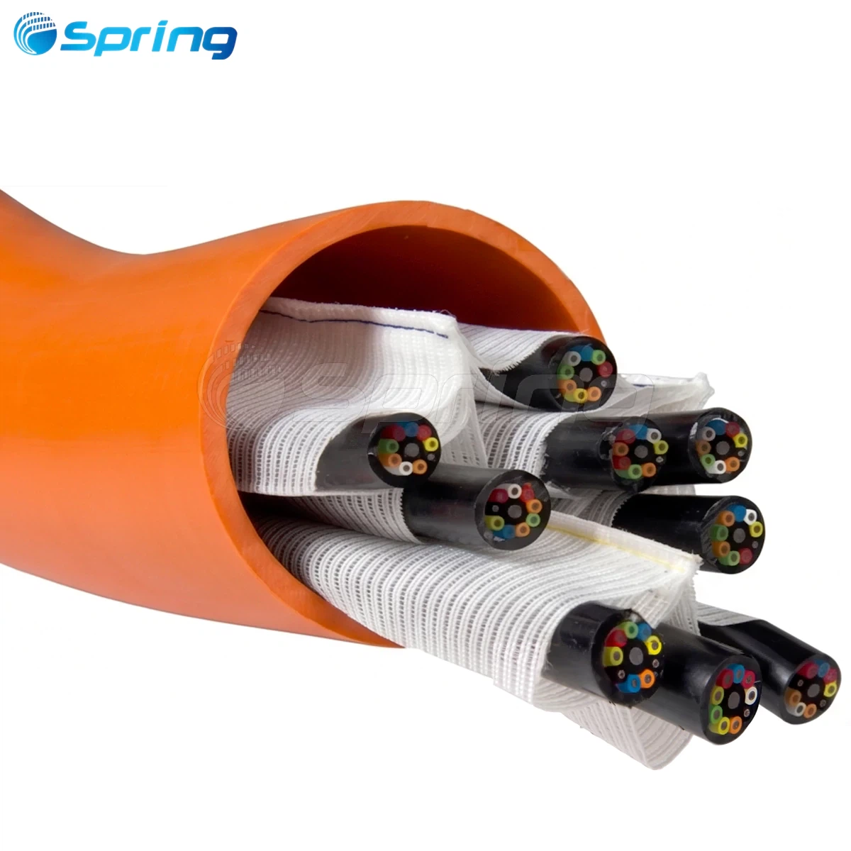
ODN or Fiber Utilisation – Because of the larger number of core fibres up taken, the material content goes up, and naturally, the number of manhours required for installation being an essential factor in the comprehensive work which the Fiber Broadband Association's Deployment Best Practices guides indicated
What is an unbalanced optical splitter? Optimizing Cascade Networks

An unbalanced optical splitter uses non-equal distribution of optical power sends more optical power to the cascade ports for further distribution and less optical power to the local drop ports. This is where the optimum cascade topology is a sine qua non in PON deployments.
Technical Example: A 1×2 unbalanced splitter might send 70% of the optical power to the cascade port (forthcoming distribution) and 30% to local user ports.
Key Characteristics of Unbalanced Splitters:
Insertion Loss: Cascade ports (70% power allocation) about 2 dB loss, local ports (30% power) about 6 dB loss
Cascade Architecture: Converts products for cascading of more than one splitter, normally a four level cascade allows 16 users from one fibre core (fiber core run between boxes) by the principles shown in FTTH Council Europe's design guidance
Fibre Efficiency: Greatly reduces the fibre onsite from / to distribution points thus reducing installation costs markedly
Balanced vs. Unbalanced Splitters: Direct Technical Comparison

Evaluation Criteria |
Balanced Splitter |
Unbalanced Splitter |
|
Power Distribution |
Equal across all ports |
Unequal (cascade vs. local) |
|
PON Topology |
Star architecture |
Chain/cascade architecture |
|
Fiber Consumption |
Higher fiber core usage |
Minimal inter-box fiber requirements |
|
Cost Considerations |
Higher material and labor costs |
Reduced installation and fiber costs |
|
Optimal Applications |
Urban high-density areas |
Rural/long-reach networks |
When to Use Balanced Splitters in FTTX Networks


Dense Urban Deployments: Highly concentrated use clusters need short-reach applications
Star Topology Applications: Networks in which the splitter serves a finite amount of subscribers directly
Uniform Power Level Applications: Those in which all endpoints need equal power levels
Most Applicable uses of Unbalanced Splitters in PON Infrastructure

1*5 Unbalanced PLC Splitter
·IL:16.8 dB.
·Min RL:55 dB.
·G657.A1 Fiber.
·1260~1650nm.
·85/15% Split Ratios.
·SC,LC,FC Connector.

1*9 Unbalanced PLC Splitter
·IL:16.5 dB.
·Min RL:55 dB.
·G657.A1 Fiber.
·1260~1650nm.
·70/30% Split Ratios.
·SC, LC,FC Connector.

1*17 Unbalanced PLC Splitter
·IL:19.7dB.
·Min RL:55 dB.
·G657.A1 Fiber.
·1260~1650nm.
·70/30% Split Ratios.
·SC,LC,FC Connector.
Long-haul Applications: Especially appropriate for being cascaded along streets or fiber aerial lines
Rural Applications: Richly serves geographically separated subscribers with minimal fiber infrastructure. Advances the effort of the U.S. Rural Digital Opportunity Fund
Large Residential Use: This includes deployments in villas, multi-dwelling units (MDUs) and campus-like combinations where single fiber cores provide multiple endpoints through cascaded splitting
High Rise Building Networks: Allows for cascading of signaling over multiple floors per building through optimization of back-bone fiber
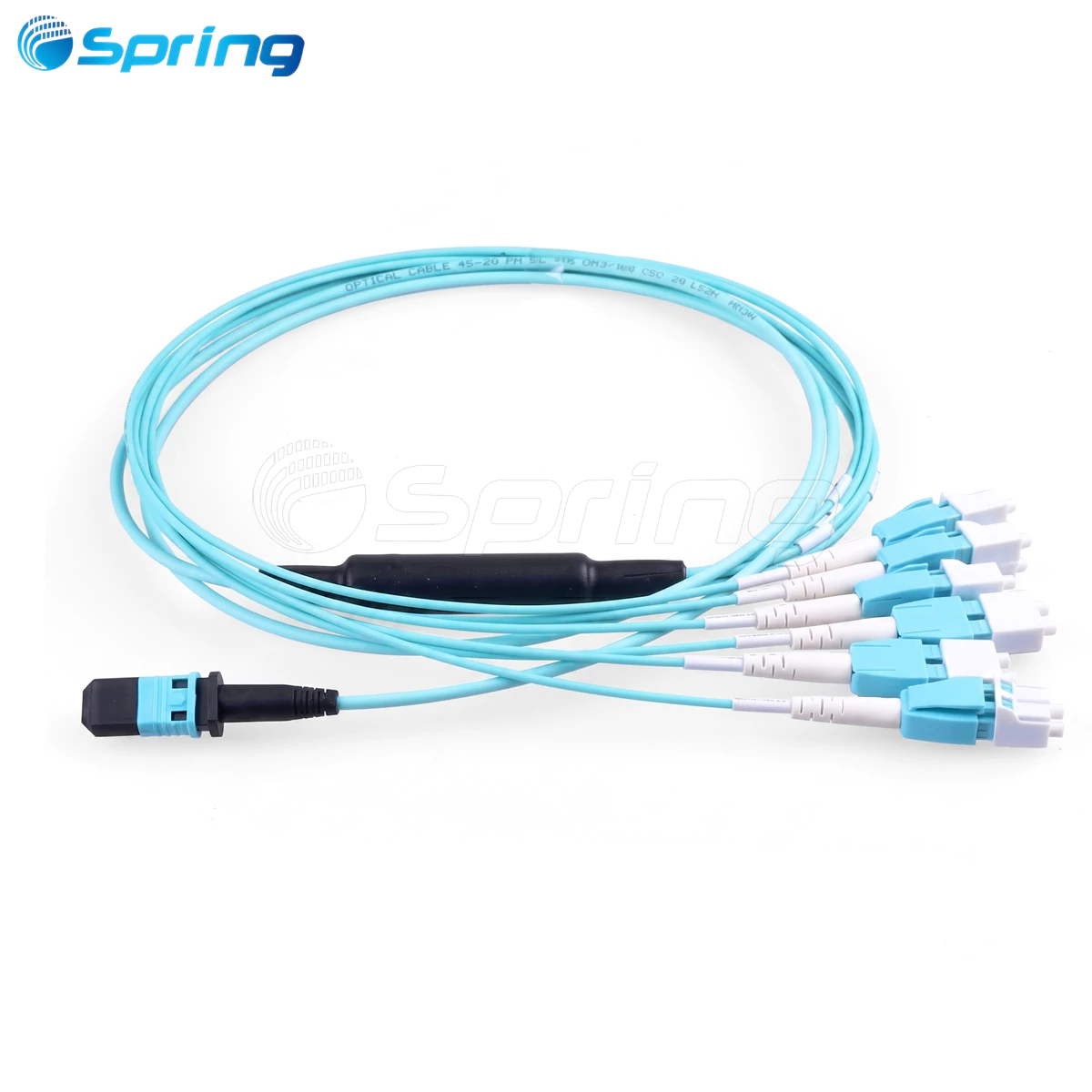
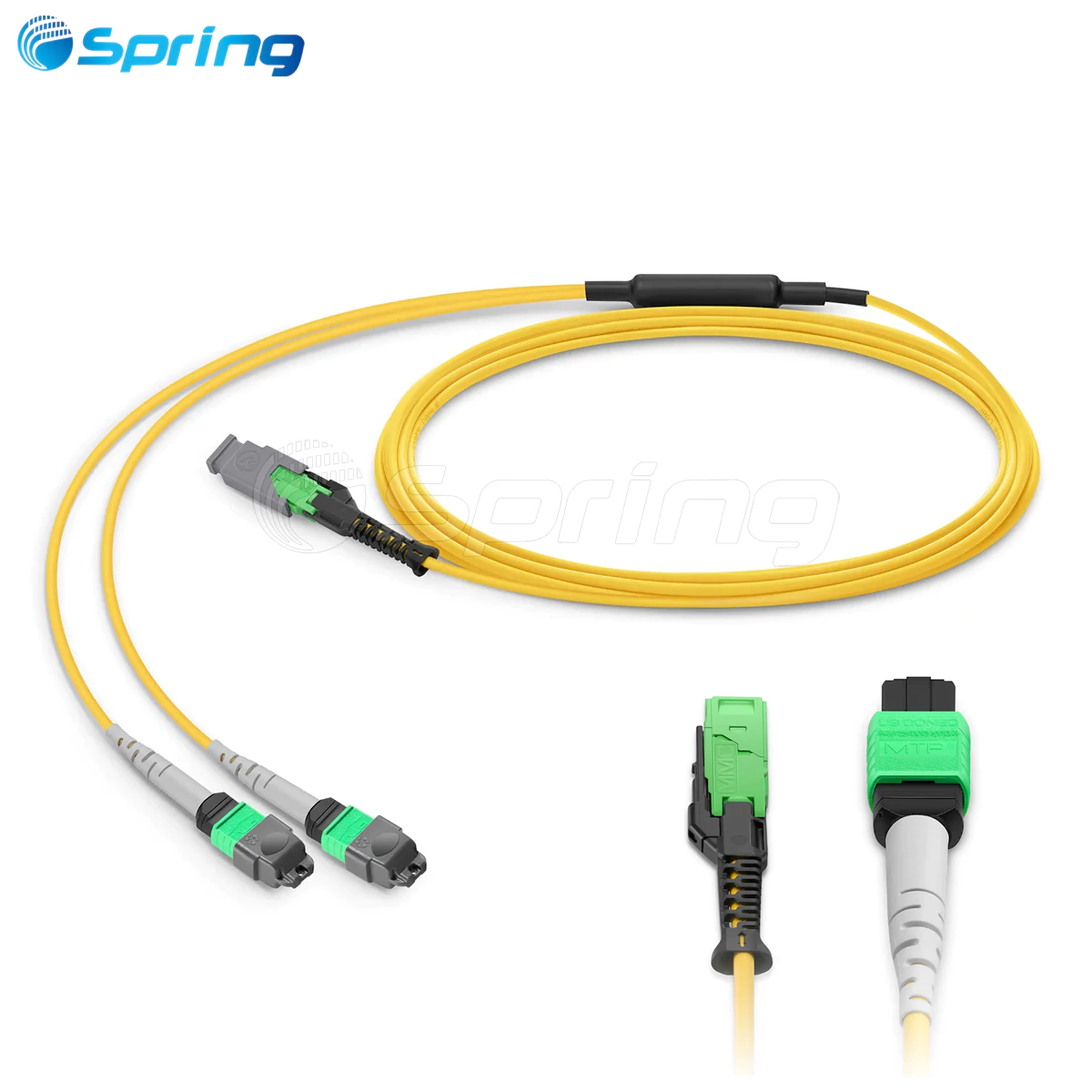
Pre-Connectorized ODN Access Solutions: Accelerating Both Types of Splitter
Modern pre-connectorized optical distribution boxes transform splitter installation by including factory-terminated components to ruggedized, environmental housings. They thereby greatly improve installation efficiency of balanced and unbalanced splitter designs.

How Pre-Connectorized ODN Solutions Work:
Plug-and-Play: Factory-assembled splitter modules with connectorized pigtails eliminate need for field fusion splicing
Tested Devices: Each splitter and connector is rigorously pre-tested for their insertion loss values and signal performance, per IEC 61753-1 performance standards
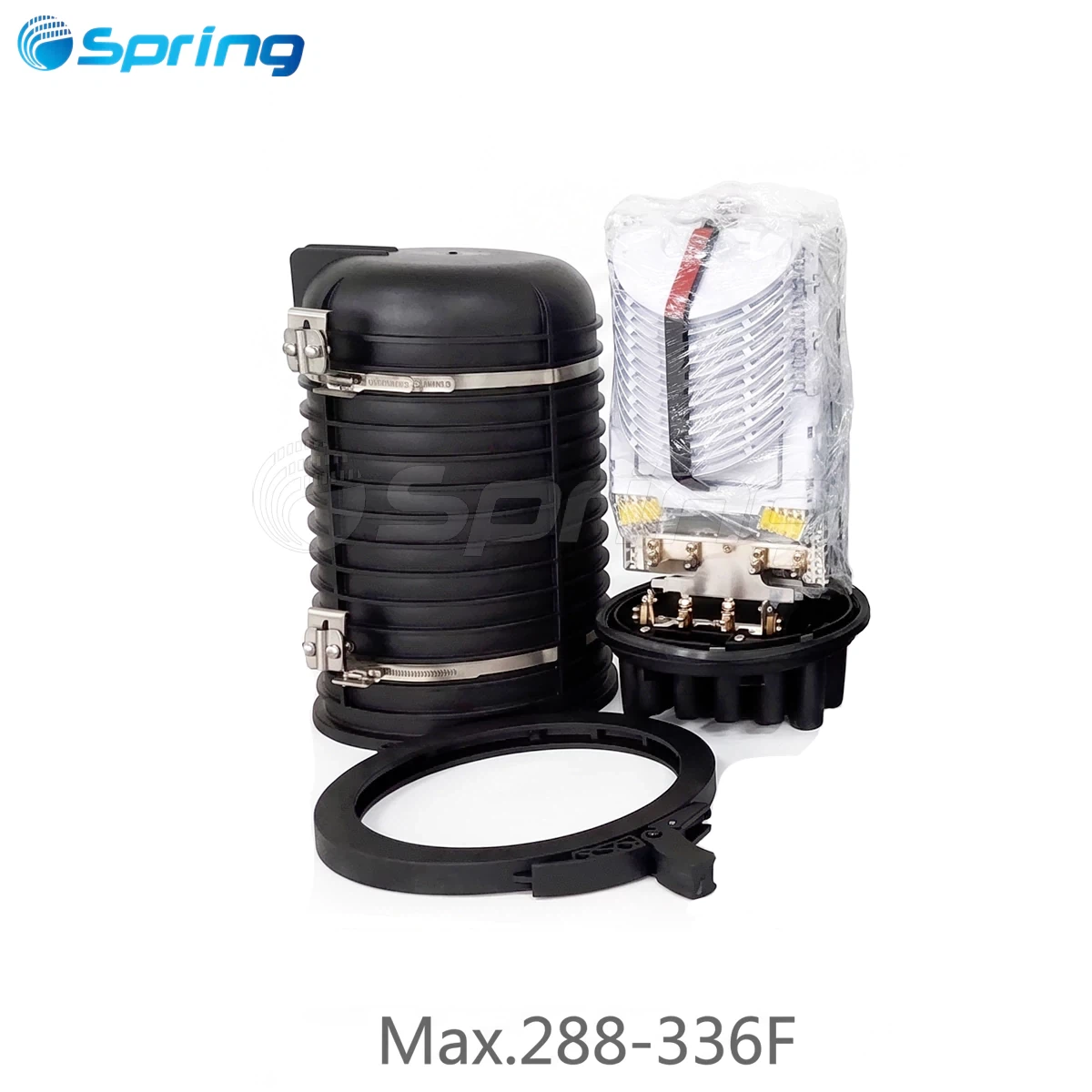
Protection Mechanism: IP68-rated housing protects reliable functioning in outdoor environments with several mounting options
Configurability: Allows balanced splitter modules for star topologies and unbalanced splitter modules for cascade-type architectures
Benefits of Pre-Connectorized Fiber Distribution Boxes:
Faster FTTX Deployment: Installation time is reduced by as much as 60% when compared to solutions involving field splicing
Less Cost for Labor: Greatly reduces requirement of highly-skilled splicing technicians
Greater Reliability: Reduced field errors resulting from factory testing and termination
Scalable Network Infrastructure: Supports to 18 drop ports in one enclosure in a variety of splitter ratios
Conclusion: Selecting the Right Splitter Strategy for Your ODN
Balanced optical splitters should be selected for star topology PONs with high user density and short reach requirements. In these applications, the cost of fiber is secondary to ease of deployment.
Unbalanced optical splitters should be chosen for cascade-based optical network architectures which require long reach or a high degree of fiber utilization in a branched network environment.
In either instance, the splitter configuration used in combination with SpringOptical's pre-connectorized optical distribution systems gives the network operator the capability for optimized FTTX deployments that allow balanced performance, finances and expansion capabilities with prompt and error-free installs.
Readers requiring detailed technical specifications for their commercial deployment should refer to supplier documentation available from any of the industry leaders such as Corning Optical Communications or CommScope.