

Introduction
As global demand for broadband bandwidth accelerates across FTTH, 5G, and enterprise networks, traditional fiber optic cabling encounters severe bottlenecks: crowded underground ducts, high initial civil infrastructure CAPEX, and long deployment cycles.
Air Blown Fiber (ABF) technology-also known as microduct blown fiber-solves these challenges by physically separating duct installation from fiber deployment. Instead of pulling heavy, rigid fiber cables through conduits, light micro-cables or fiber units are pneumatically "blown" through pre-installed plastic microducts using compressed air.
In this technical guide, written by our senior optical engineering team at Spring Optical, we cover the working mechanics of pneumatic fiber blowing, analyze key system components, compare Air Blown Fiber vs. Traditional Cabling, evaluate Indoor Fiber Units (EPFU/SFU) against Outdoor Micro Cables (GCYFXTY/Loose Tube), provide a microduct sizing rule, and share site troubleshooting tips.
Quick Answer: What Is Air Blown Fiber (ABF)?
Air Blown Fiber (ABF) is a specialized network installation method where miniature fiber units or micro-cables are pushed and pulled through lightweight HDPE microducts using a synchronized combination of viscous air drag and mechanical pushing forces.
How Air Blown Fiber Mechanics Work
The Air Blown Fiber installation process relies on two synchronized physical forces working simultaneously inside the conduit:
Compressed Air Injection: A high-capacity mobile air compressor injects dry, cooled compressed air at 10 to 15 Bar (145–217 PSI) into the system.
Blowing Machine Engagement: The microduct blowing head combines rubber tractor wheels (mechanical push) with high-velocity airflow.
Viscous Air Drag Execution: As high-speed air flows through the enclosed microduct, viscous air drag acts uniformly along the entire cable jacket, gliding the fiber unit or micro cable seamlessly forward over long distances with minimal friction.
Essential Components of an Integrated Air Blown Fiber System

A successful Air Blown Fiber deployment relies on a fully integrated ecosystem of specialized hardware, protection closures, and installation equipment working together seamlessly:
HDPE Microducts: Lightweight, flexible conduits manufactured from High-Density Polyethylene (HDPE) with low-friction inner linings, serving as designated raceways for fiber deployment.
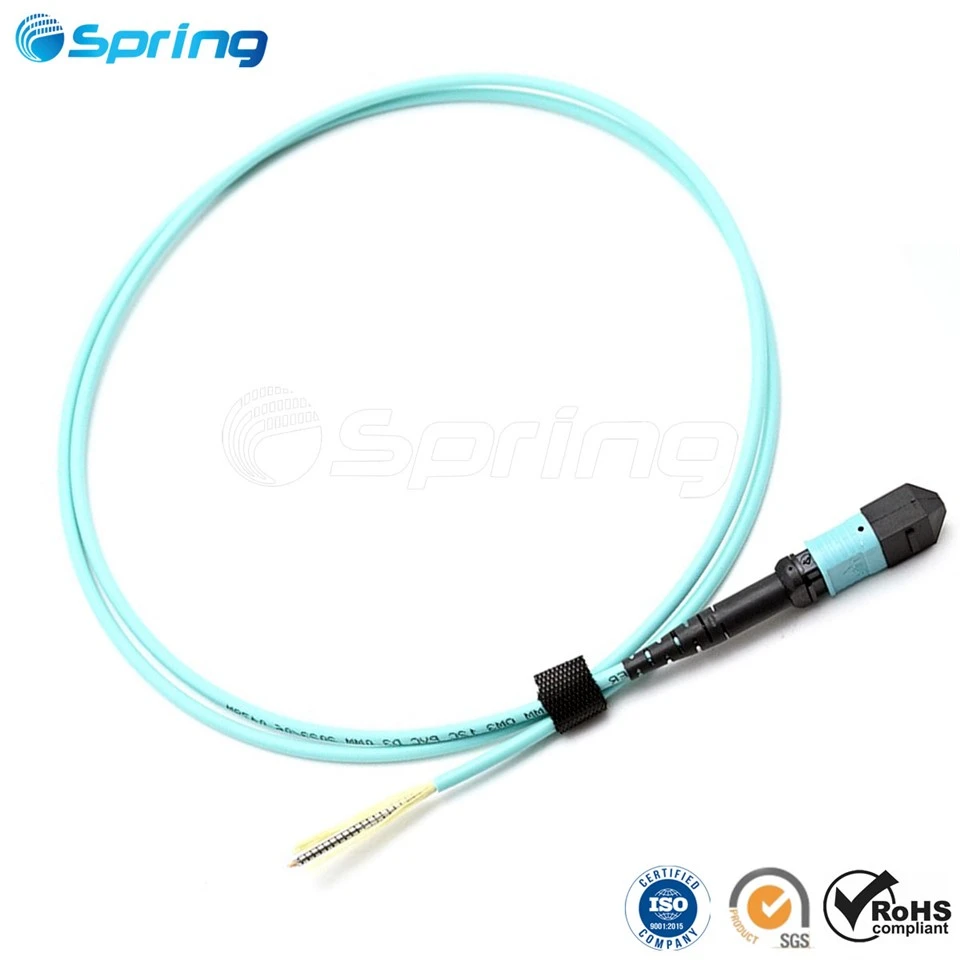
Microduct & Air Blowing Micro fiber Optic Cable: Specialized low-friction, highly flexible optical cables (including EPFU, SFU, Uni-Tube, and Stranded Micro Cables) engineered specifically to capture airflow and maximize viscous air drag.
Pneumatic Blowing Machines: Mechanical jetting equipment combining motorized rubber tractor belts (for physical push) with high-pressure air heads to propel the cable forward.
Industrial Air Compressors: Heavy-duty compressors equipped with aftercoolers and moisture separators supplying continuous dry, oil-free compressed air at 10 to 15 Bar (145–217 PSI).
Microduct Connectors & Gas-Block Seals: Precision push-fit Microduct Connectors and air-tight end caps that maintain system pressurization, prevent air leakage, and block water/gas at junction points.
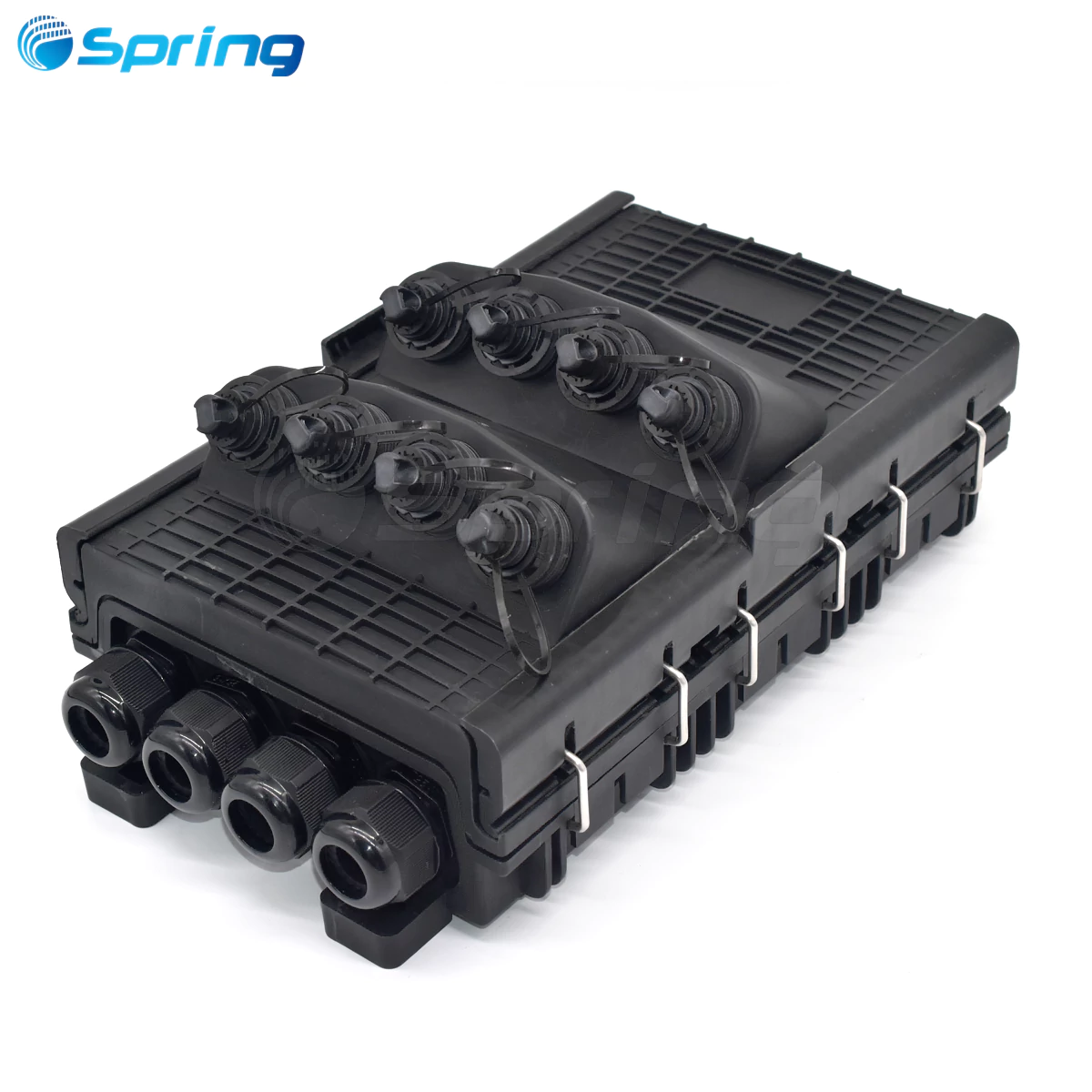
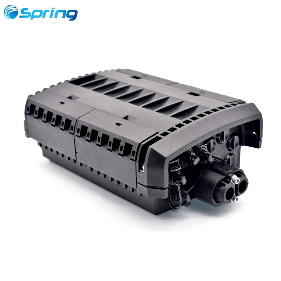
Microduct Closures & Telecom Manholes: Rugged, water-tight Microduct Closures installed inside outdoor Telecom Manholes (handholes) to protect microduct joints, strain-relief branch splits, and fiber splices from harsh environmental conditions.
Specialized Cable Lubricants: Water-based low-friction polymers applied during long-distance blowing runs to drastically minimize drag between the cable jacket and microduct inner wall.
Air Blown Fiber vs. Traditional Optical Cable Systems
To understand why network operators are migrating to ABF systems, it is essential to compare the financial and operational mechanics between conventional direct-buried/pulled cables and microduct blown fiber.
| Comparison Feature | Traditional Optical Cable Systems | Air Blown Fiber (ABF) Systems |
| Installation Method | Mechanical winching / manual pulling | Pneumatic air blowing (Viscous air drag) |
| Initial Civil CAPEX | High upfront investment in full fiber capacity | Low initial cost; install microducts first, blow fiber as needed |
| Installation Tensile Stress | High localized pull tension (risk of fiber damage) | Virtually zero tensile strain distributed uniformly |
| Duct Space Utilization | Occupies 80%–90% of main conduit space | Multi-tubular microducts maximize duct capacity by up to 300% |
| Future Upgrade Path | Requires costly civil excavation & trenching | Simple depressurization, cable blowout, and quick blow-in |
| Fiber Branching Flexibility | Complex inline splicing at main handholes | Simple push-fit connectors at branch distribution points |


Microduct Sizing Calculation: The 50%-60% Rule
To ensure maximum pneumatic blowing distance and prevent cable jamming, engineers must strictly adhere to the Cable-to-Duct Fill Ratio Rule:
Fill Ratio (%) = (Cable Outer Diameter / Microduct Inner Diameter) × 100%
Optimal Target Ratio: 50% to 60%
Maximum Limit: 65% (Ratios above 65% drastically reduce airflow velocity and limit blowing distance)
Recommended Cable and Microduct Matchings
1.1 mm – 1.6 mm EPFU / SFU: Pairs with 5/3.5 mm or 7/5.5 mm Microducts
2.0 mm – 3.5 mm Uni-Tube Micro Cable: Pairs with 8/6 mm or 10/8 mm Microducts
5.0 mm – 7.5 mm Stranded Micro Cable: Pairs with 12/10 mm or 14/10 mm Microducts
Technical Selection: Fiber Units (EPFU/SFU) vs. Micro Cables
Choosing the correct air-blown fiber product depends heavily on fiber density requirements, mechanical crush targets, and deployment environments (indoor drop vs. outdoor backbone).


Quick Selection Matrix
| Fiber Cable Type | Construction & Sheath Material | Core Count | Outer Diameter (OD) | Max Blowing Distance | Primary Application |
| EPFU (Enhanced Fibre Unit) | Low-friction dimpled acrylate resin | 2–12 Cores | 1.1 mm – 1.6 mm | Up to 1,000 m | FTTH indoor drops, high-density MDU risers |
| SFU (Smooth Fibre Unit) | Thermoplastic smooth outer sheath | 2–12 Cores | 1.2 mm – 1.8 mm | Up to 1,200 m | Enterprise LAN, indoor/outdoor microducts |
| Uni-Tube Micro Cable (GCYFXTY) | Central loose tube, water-blocking yarn, HDPE sheath | 2–24 Cores | 2.0 mm – 3.5 mm | Up to 1,500 m | Outdoor access networks, city microduct branches |
| Loose Tube Micro Cable | Stranded multi-loose tube, HDPE low-friction sheath | 24–288 Cores | 4.5 mm – 9.5 mm | Up to 2,000 m+ |
Metro backbones, long-haul FTTx feeder links |
Detailed Product Breakdown: Matching Cables to Applications
1. Indoor & Last-Mile Drop: EPFU & SFU Fiber Units
For indoor FTTH installations, enterprise LAN cabling, or vertical riser shafts where duct space is extremely confined, ultra-lightweight fiber units are preferred.
EPFU (Enhanced Performance Fibre Units)
Designed for optimum aerodynamic drag inside indoor microducts.
Surface Technology: Features a specially textured, dimpled acrylate coating that captures airflow efficiently, drastically reducing friction along microduct walls.
Key Advantage: Extremely small outer diameter allows up to 12 fibers in a 1.5 mm profile.
Best Use Case: EPFU Fiber Units excel in last-mile FTTH indoor drops, campus networks, and MDU riser shafts.
SFU (Smooth Fibre Unit)
Engineered with a high-density, smooth thermoplastic skin for added mechanical toughness.
Surface Technology: Low-coefficient-of-friction polymer compound providing robust physical protection during high-speed blowing.
Key Advantage: Enhanced mechanical protection against micro-bending while maintaining flexibility around tight indoor conduit turns.
Best Use Case: SFU Smooth Fibre Units are ideal for commercial building risers, horizontal LAN distribution, and data center pathways.
2. Outdoor & Metro Backbone: Air-Blown Micro Cables
When expanding metro access networks or interconnecting outdoor cell sites, micro-cables provide higher fiber counts, UV protection, and enhanced crush resistance (tested per IEC 60794-1-2 E3).
Uni-Tube Air Blown Micro Cable (GCYFXTY)
A compact central-tube design optimized for outdoor microduct access paths.
Construction: Contains optical fibers within a central jelly-filled loose tube, wrapped with water-blocking yarn and encased in a durable HDPE sheath.
Key Advantage: Outstanding balance between compact diameter and crush resistance (up to 500 N/100mm).
Best Use Case: Uni-Tube GCYFXTY Cables serve as the backbone for FTTx distribution loops and suburban drop routes.
Stranded Loose Tube Air-Blown Micro Cable
High-density backbone cables designed for maximum fiber capacity in limited duct spaces.
Construction: Multi-loose tube stranded design around a Central Strength Member (CSM) with a ultra-low-friction outer PE jacket.
Key Advantage: High fiber counts (up to 288 cores) in a diameter 50% smaller than traditional direct-buried fiber cables.
Best Use Case: Stranded Loose Tube Micro Cables are built for long-distance pneumatic blowing (>2,000 m) across municipal metro networks and inter-datacenter (DCI) links.
Engineering Field Guide: Troubleshooting Common Air Blowing Issues
During pneumatic cable installation, field technicians may encounter sudden friction spikes or stoppage. Here is how Spring Optical's engineering team recommends resolving common site challenges:
| Issue | Probable Cause | Recommended Solution |
| Sudden Cable Stoppage | Microduct kink or tight bend along the route | Perform a sponge test and verify the duct bend radius |
| Reduced Blowing Distance | Air pressure loss or loose duct couplings | Inspect gas-block connectors and ensure compressor maintains stable pressure |
| Cable Buckling at Head | Excessive mechanical pushing force | Lower the mechanical pushing speed and adjust torque settings on the blowing machine |
Field Best Practices
Pre-Blowing Sponge Test: Always blow a foam sponge and calibration mandrel through the microduct before cable insertion to verify duct continuity and clean out moisture or debris.
Temperature Control: Air leaving the compressor must pass through an aftercooler; air temperature inside the microduct must not exceed 40°C (104°F) to prevent HDPE jacket softening.
Frequently Asked Questions (FAQ)
What is the maximum distance Air Blown Fiber can be installed in one run?
Depending on the cable outer diameter, microduct inner diameter, and route bends, lightweight fiber units (EPFU/SFU) can be blown up to 1,000 m to 1,200 m. Heavy-duty outdoor Micro-Cables can reach 2,000 meters or more in a continuous blowing cycle at 12–15 Bar pressure.
What is the difference between EPFU and an Air-Blown Micro Cable?
EPFU (Enhanced Performance Fibre Unit) features a compact 2–12 core acrylate structure tailored for short-to-medium distance indoor/FTTH drops. Micro Cables incorporate central or stranded loose-tube designs with HDPE jackets, supporting up to 288 cores for rugged outdoor metro links.
How do you choose the right microduct size for an air-blown cable?
Maintain a Cable-to-Duct Ratio between 50% and 60%. For example, a micro-cable with a 3.0 mm outer diameter works best in a microduct with an inner diameter (ID) of 5.0 mm to 6.0 mm. This ensures optimal airflow clearance and maximum aerodynamic drag.
What standards govern Air Blown Fiber products?
All professional air-blown fiber products should strictly comply with IEC 60794-5 (Optical fibre cables - Sectional specification for microduct cabling) and IEC 60794-1-2 for mechanical and environmental testing.
High-Performance Air Blown Fiber Solutions from Spring Optical
Selecting high-quality microduct cables and fiber units is critical to avoiding pneumatic installation failures and maximizing blowing distance.
Spring Optical (Shenzhen Spring Optical Communication Co., Ltd.) provides a full range of air-blown fiber solutions engineered for global telecom operators, ISPs, and FTTH contractors.
Why Choose Spring Optical?
Complete Product Portfolio: From 2-core EPFU and SFU indoor units to 288-core outdoor Micro Cables.
Strict Quality Assurance: All cables feature low-friction jackets, fully compliant with IEC 60794-5 air-blowing standards and tested for mechanical crush, tensile strength, and temperature cycling.
OEM/ODM Customization: Custom color coding, jacket printing, packaging lengths, and specialized outer diameters tailored to your specific microduct infrastructure.
Need technical datasheets, IEC test reports, or sample kits for your upcoming network rollout?
Contact Spring Optical Engineering Team to request custom factory quotes and expert air-blowing installation guidance today.