1. Scope of Application
Applicable for overhead, underground, pipeline, and handhole fiber optic splicing.
Environmental temperature range: -40℃ to 65℃
2. Basic Structure and Configuration
Dimensions: 455mm (height) × 220mm (diameter)
Weight: 3.0–3.6kg
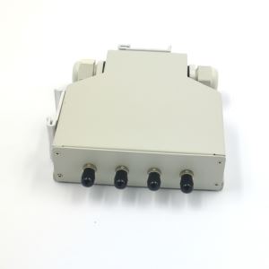
Number of cable ports: typically 8 (up to 10)
Applicable cable diameter: Φ8mm–Φ36mm
Capacity: 12–240 fibers for bundle type, up to 576 fibers for ribbon type
Main Components
FOSC cover
Fiber optic splice trays (up to 10)
Base
Plastic clamp
Sealing components
Pressure testing the valve
Grounding device
Accessories and Special Tools
Heat-shrink protective sleeves
Nylon cable ties
Branch clips
Grounding wires
Desiccant
Label paper
Special wrench
Metal clamp
Aluminum foil, etc.
3. Tools Required for Installation
Fiber optic cleaver
Fiber stripper
Combination tools
Measuring tape
Tube cutter
Pliers
Screwdrivers, etc.
Fusion splicer, OTDR tester, and other splicing and testing equipment
4. Installation Process Summary
4.1 Opening the Closure
Check the environment and set up a protective tent if necessary.
Remove the plastic clamp and take off the cover.
(See drawing 1)

4.2 Determine Cable Stripping Length
Determine the stripping length based on the branch or straight-through method, referring to the diagram.
(See drawing 2)

4.3 Remove Cable Sheath
Use a cutter and stripper to remove the sheath in sections, avoiding fiber breakage.
(See drawing 3)

4.4 Prepare Fiber Cores
Wrap the fiber with insulation tape for protection and clean out filler materials.
Sort the fibers based on branch or straight-through classification.
(See drawing 4)

4.5 Fix Strength Members and Seal Cable
Insert the heat shrink tube and heat to seal; tighten the strength member nut with the special wrench.
(See drawing 5)

4.6 Splice the Fibers
Follow the fusion splicer's manual, ensuring no twisting or bending of the fibers.
(See drawing 6)

4.7 Install Splice Protectors and Fiber Tray
Secure the splice protectors and fiber coils in sequence on the splice tray.
(See drawing 7)

4.8 Final Check and Confirmation
Ensure all cable ties, seals, and nuts are properly secured.
Check the integrity of the sealing and fiber routing.
(See drawing 8)

4.9 Assemble the Closure Housing
Place the cover, install and tighten the plastic clamp.
Fix the closure on the pole, wall, or underground as needed.
5. Inspection and Testing Items
Appearance intact, clear identification.
Fiber storage length and bending radius comply with standards.
Sealing performance passes 100kPa air pressure immersion test.
Mechanical strength meets tension, impact, and compression requirements.
Grounding device functions properly.
Spring Optical Communication is one of the largest and best GJS-D008 fiber optical vertical joint splice closure box manufacturers and suppliers with rich experience. Welcome to buy our high-quality products or wholesale our customized GJS-D008 fiber optical vertical joint splice closure box in stock from our factory. Also, a free sample is available if necessary.
Hot Tags: Dome Closure GJS-D008 manufacturers, suppliers, factory, wholesale, customized, buy, bulk, in stock, free sample